PARK ASSIST / MONITORING PARKING ASSIST MONITOR SYSTEM CALIBRATION
ADJUST PARKING ASSIST MONITOR SYSTEM
The parking assist monitor system can be adjusted using diagnostic mode.
If the following operations are performed, it is necessary to perform adjustments and checks using diagnostic mode.
| Part Name | Operation | Adjustment Item | Proceed to |
|---|---|---|---|
| Suspension, tires, etc. | Replacement (The vehicle height changes due to suspension or tire replacement) | Rear television camera assembly optical axis (Back camera position setting) | Procedure 2 |
| Rear television camera assembly | Replacement | Parking assist monitor system initialization | Procedure 1 |
| Removal and installation of the rear television camera assembly etc. (Installation angle of the rear television camera assembly changes due to removal and installation) | Rear television camera assembly optical axis (Back camera position setting) | Procedure 2 |
- HINT:
-
The adjustment values stored while performing parking assist monitor system calibration are stored in the rear television camera assembly.
PARKING ASSIST MONITOR SYSTEM INITIALIZATION (PROCEDURE 1)
- HINT:
- ·
Be sure to check for DTCs before performing this procedure.
·Illustrations may differ from the actual vehicle screen depending on the device settings and options. Therefore, some detailed areas may not be shown exactly the same as on the actual vehicle screen.
Preparation for adjustment
Park the vehicle with the steering wheel centered.
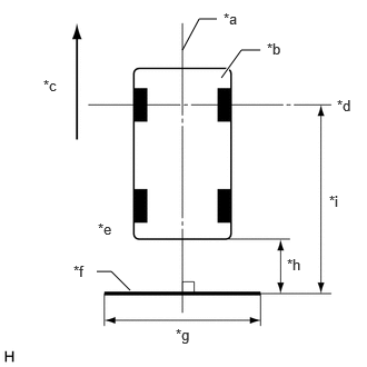
| *a | Vehicle Center |
| *b | Vehicle |
| *c | Front |
| *d | Front Wheel Axis |
| *e | Vehicle End |
| *f | Target Bar for Back Camera Adjustment |
| *g | 2000 mm (6.56 ft.) |
| *h | A |
| *i | B |
Set a target bar behind the vehicle for optical axis adjustment of the rear television camera assembly (back camera position setting).
- HINT:
-
Create a target bar for adjustment only when adjusting the optical axis of the rear television camera assembly.
- Dimension:
A B 1000 mm (3.28 ft.) 4506 mm (14.78 ft.)
- HINT:
- ·
Set a piece of tape on the ground as the target bar for adjustment. Its width and length should be 20 to 30 mm (0.787 to 1.180 in.) and 1995 to 2005 mm (6.544 to 6.576 ft.), respectively. Check the color on the radio and display receiver assembly and choose a tape color which can be easily seen.
·Before parking the vehicle, be sure to move the vehicle forward and in reverse to check that the tires are facing straight ahead with the steering wheel centered.
·Check that the back door is fully closed.
Start diagnostic mode.
for TFTM Made: Click hereAudio / Visual / Telematics>NAVIGATION / MULTI INFO DISPLAY>NAVIGATION SYSTEM (Production Date from 2023/04)>DIAGNOSIS SYSTEM202201,999999,_56,_111967,_0588532,RM1000000029ZSR,
for GTMC Made: Click hereAudio / Visual / Telematics>AUDIO / VIDEO>AUDIO AND VISUAL SYSTEM (Production Date from 2023/04)>DIAGNOSIS SYSTEM202405,999999,_56,_111966,_0589552,RM100000002MH8J,
- NOTICE:
-
The following must be carried out with start the hybrid control system. Apply the parking brake, depress the brake pedal, check that the shift position is in P, and ensure that the vehicle is not moving.
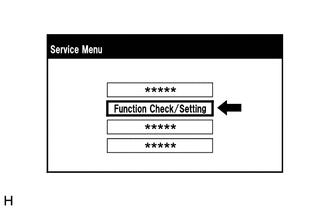
Select "Function Check/Setting" on the "Service Menu" screen.
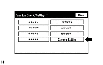
Select "Camera Setting" on the "Function Check/Setting I" screen.
- NOTICE:
-
If the "Camera Setting" selection screen is not displayed, turn the ignition switch off and enter the diagnosis screen after turning the ignition switch to ON once again.
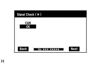
Select "Next" on the "Signal Check (*)" screen.
- HINT:
- ·
When "CHK" (red) is displayed for any items on the "Signal Check (*)" screen, selecting "Next" will not change the screen to the "Steering Angle Setting D (*)" screen.
·When "CHK" (red) is displayed for any items on the "Signal Check (*)" screen, perform inspections using the "Signal Check (*)" screen.
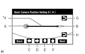
| *a | Target Bar for Back Camera Position Setting |
Back Camera Position Setting (Both Ends of Target Bar)
- HINT:
- ·
When the back door is open, "You can not calibrate the camera when the door is open. Please close the door" message will be displayed and it will not be possible to perform back camera position setting.
·Even when the back door is closed and "You can not calibrate the camera when the door is open. Please close the door." is displayed, refer to Problem Symptoms Table and check the cause of the malfunction.
Perform vertical and horizontal position adjustment.
Move circle A left, right, up and down by selecting buttons C, D, E and F so that the left end of the target bar for back camera position setting is positioned within the center of circle A (center of the inner red circle).
Perform roll angle adjustment.
Rotate bar B by selecting buttons G or H so that bar B becomes parallel to target bar for back camera position setting.
Select "Next" on the "Back Camera Position Setting D (*)" screen.
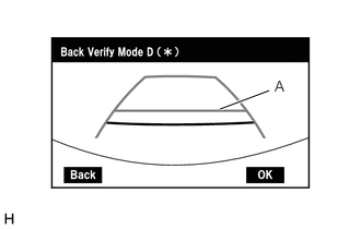
Back Verify Mode
Check that A and the target adjustment bar are overlapping.
If A and the target adjustment bar are not aligned even if the tires are aligned straight ahead, perform the back camera position setting operation.
Select "OK" to return to the "Function Check/Setting I" screen and complete the adjustment.
- HINT:
- ·
The update is not completed until "OK" is selected.
·When "OK" is selected, a beep will sound to confirm that the adjustment values have been stored.
·The adjustment values are not stored until the beep has sounded.
Finish diagnostic mode.
for TFTM Made: Click hereAudio / Visual / Telematics>NAVIGATION / MULTI INFO DISPLAY>NAVIGATION SYSTEM (Production Date from 2023/04)>DIAGNOSIS SYSTEM202201,999999,_56,_111967,_0588532,RM1000000029ZSR,
for GTMC Made: Click hereAudio / Visual / Telematics>AUDIO / VIDEO>AUDIO AND VISUAL SYSTEM (Production Date from 2023/04)>DIAGNOSIS SYSTEM202405,999999,_56,_111966,_0589552,RM100000002MH8J,
BACK CAMERA POSITION SETTING (PROCEDURE 2)
- HINT:
- ·
Be sure to check for DTCs before performing this procedure.
·Illustrations may differ from the actual vehicle screen depending on the device settings and options. Therefore, some detailed areas may not be shown exactly the same as on the actual vehicle screen.
| *a | Vehicle Center |
| *b | Vehicle |
| *c | Front |
| *d | Front Wheel Axis |
| *e | Vehicle End |
| *f | Target Bar for Back Camera Adjustment |
| *g | 2000 mm (6.56 ft.) |
| *h | A |
| *i | B |
- Dimension:
A B 1000 mm (3.28 ft.) 4506 mm (14.78 ft.)
Preparation for adjustment
Park the vehicle with the steering wheel centered.
Set a target bar behind the vehicle for optical axis adjustment of the rear television camera assembly (back camera position setting).
- HINT:
-
Create a target bar for adjustment only when adjusting the optical axis of the rear television camera assembly.
- HINT:
- ·
Set a piece of tape on the ground as the target bar for adjustment. Its width and length should be 20 to 30 mm (0.787 to 1.180 in.) and 1995 to 2005 mm (6.544 to 6.576 ft.), respectively. Check the color on the radio and display receiver assembly and choose a tape color which can be easily seen.
·Before parking the vehicle, be sure to move the vehicle forward and in reverse to check that the tires are facing straight ahead with the steering wheel centered.
·Check that the back door is fully closed.
Start diagnostic mode.
for TFTM Made: Click hereAudio / Visual / Telematics>NAVIGATION / MULTI INFO DISPLAY>NAVIGATION SYSTEM (Production Date from 2023/04)>DIAGNOSIS SYSTEM202201,999999,_56,_111967,_0588532,RM1000000029ZSR,
for GTMC Made: Click hereAudio / Visual / Telematics>AUDIO / VIDEO>AUDIO AND VISUAL SYSTEM (Production Date from 2023/04)>DIAGNOSIS SYSTEM202405,999999,_56,_111966,_0589552,RM100000002MH8J,
- NOTICE:
-
The following must be carried out with start the hybrid control system. Apply the parking brake, depress the brake pedal, check that the shift position is in P, and ensure that the vehicle is not moving.
Select "Function Check/Setting" on the "Service Menu" screen.
Select "Camera Setting" on the "Function Check/Setting I" screen.
- NOTICE:
-
If the "Camera Setting" selection screen is not displayed, turn the ignition switch off and enter the diagnosis screen after turning the ignition switch to ON once again.
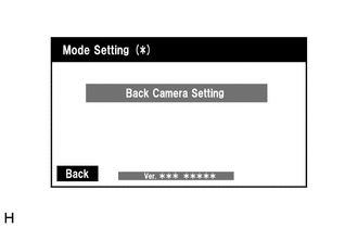
Select "Back Camera Setting" on the "Mode Setting (*)" screen.
- HINT:
-
To select a grayed out item, select and hold the item for 2 seconds or more.
Select "Next" on the "Signal Check (*)" screen.
- HINT:
- ·
When "CHK" (red) is displayed for any items on the "Signal Check (*)" screen, selecting "Next" will not change the screen to the "Back Camera Position Setting D (*)" screen.
·When "CHK" (red) is displayed for any items on the "Signal Check (*)" screen, perform inspections using the "Signal Check (*)" screen.
| *a | Target Bar for Back Camera Position Setting |
Back Camera Position Setting (Both Ends of Target Bar)
- HINT:
- ·
When the back door is open, "You can not calibrate the camera when the door is open. Please close the door." message will be displayed and it will not be possible to perform back camera position setting.
·Even when the back door is closed and "You can not calibrate the camera when the door is open. Please close the door." is displayed, refer to Problem Symptoms Table and check the cause of the malfunction.
Perform vertical and horizontal position adjustment.
Move circle A left, right, up and down by selecting buttons C, D, E and F so that the left end of the target bar for back camera position setting is positioned within the center of circle A (center of the inner red circle).
Perform roll angle adjustment.
Rotate bar B by selecting buttons G or H so that bar B becomes parallel to the target bar for back camera position setting.
Select "Next" on the "Back Camera Position Setting D (*)" screen.
Back Verify Mode
Check that A and the target adjustment bar are overlapping.
If A and the target adjustment bar are not aligned even if the tires are aligned straight ahead, perform the back camera position setting operation.
Select "OK" to return to the "Mode Setting (*)" screen and complete the adjustment.
- HINT:
- ·
The update is not completed until "OK" is selected.
·When "OK" is selected, a beep will sound to confirm that the adjustment values have been stored.
·The adjustment values are not stored until the beep has sounded.
Finish diagnostic mode.
for TFTM Made: Click hereAudio / Visual / Telematics>NAVIGATION / MULTI INFO DISPLAY>NAVIGATION SYSTEM (Production Date from 2023/04)>DIAGNOSIS SYSTEM202201,999999,_56,_111967,_0588532,RM1000000029ZSR,
for GTMC Made: Click hereAudio / Visual / Telematics>AUDIO / VIDEO>AUDIO AND VISUAL SYSTEM (Production Date from 2023/04)>DIAGNOSIS SYSTEM202405,999999,_56,_111966,_0589552,RM100000002MH8J,