LIGHTING (INT) LIGHTING SYSTEM Rear Door Courtesy Switch Circuit
DESCRIPTION
The main body ECU (multiplex network body ECU) detects the condition of the rear door courtesy light switch assembly.
WIRING DIAGRAM
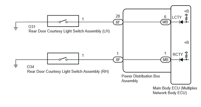
CAUTION / NOTICE / HINT
- NOTICE:
-
Before replacing the main body ECU (multiplex network body ECU), refer to Service Bulletin.*1
*1: w/ Smart Entry and Start System
PROCEDURE
Read the Data List according to the display on the GTS.
- Body Electrical > Main Body > Data List
-
Tester Display Measurement Item Range Normal Condition Diagnostic Note RR Door Courtesy Switch Status Rear door courtesy light switch assembly (RH) signal CLOSE or OPEN CLOSE: Rear door RH closed
OPEN: Rear door RH open- RL Door Courtesy Switch Status Rear door courtesy light switch assembly (LH) signal CLOSE or OPEN CLOSE: Rear door LH closed
OPEN: Rear door LH open-
- Body Electrical > Main Body > Data List
-
Tester Display RR Door Courtesy Switch Status RL Door Courtesy Switch Status - 50003 449 32,33
- OK:
Normal conditions listed above are displayed.
- Result:
Result Proceed to OK A NG ("RL Door Courtesy Switch Status" is not normal) B NG ("RR Door Courtesy Switch Status" is not normal) C
A
B
C
- Result:
Proceed to OK NG
OK
NG
Disconnect the 8F power distribution box assembly connector.
Measure the resistance according to the value(s) in the table below.
- Standard Resistance:
Tester Connection Condition Specified Condition O31-1 - 8F-28 Always Below 1 Ω O31-1 - Body ground Always 10 kΩ or higher 8F-28 - Body ground Always 10 kΩ or higher
- Result:
Proceed to OK NG
OK
NG
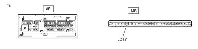
| *a | Component without harness connected
(Power Distribution Box Assembly) |
- | - |
Remove the main body ECU (multiplex network body ECU) from the power distribution box assembly.
Measure the resistance according to the value(s) in the table below.
- Standard Resistance:
Tester Connection Condition Specified Condition 8F-28 - MB-6 (LCTY) Always Below 1 Ω
- Result:
Proceed to OK NG
OK
NG
- Result:
Proceed to OK NG
OK
NG
Disconnect the 8F power distribution box assembly connector.
Measure the resistance according to the value(s) in the table below.
- Standard Resistance:
Tester Connection Condition Specified Condition O34-1 - 8F-1 Always Below 1 Ω O34-1 - Body ground Always 10 kΩ or higher 8F-1 - Body ground Always 10 kΩ or higher
- Result:
Proceed to OK NG
OK
NG
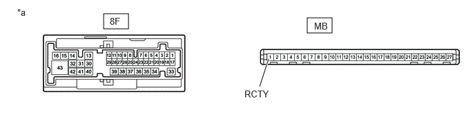
| *a | Component without harness connected
(Power Distribution Box Assembly) |
- | - |
Remove the main body ECU (multiplex network body ECU) from the power distribution box assembly.
Measure the resistance according to the value(s) in the table below.
- Standard Resistance:
Tester Connection Condition Specified Condition 8F-1 - MB-1 (RCTY) Always Below 1 Ω
- Result:
Proceed to OK NG
OK
NG