RM38T0EC
_59
Vehicle Exterior
_114146
WIPER / WASHER
_0510034
WIPER AND WASHER SYSTEM
J
WIPER / WASHER WIPER AND WASHER SYSTEM Rear Wiper Motor Circuit
DESCRIPTION
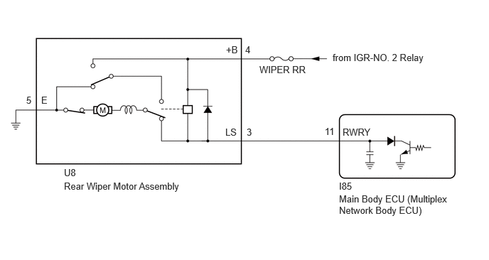
This circuit is the power source circuit for the rear wiper motor assembly.
WIRING DIAGRAM
0.604,1.385 0.76,1.583
0.156,0.198
10
false
E
3.313,0.646 3.625,0.844
0.313,0.198
10
false
+B
3.594,0.646 3.75,0.844
0.156,0.198
10
false
4
0.385,1.385 0.542,1.583
0.156,0.198
10
false
5
3.302,1.854 3.615,2.052
0.313,0.198
10
false
LS
4.76,1.844 4.99,2.042
0.229,0.198
10
false
11
3.615,1.854 3.771,2.052
0.156,0.198
10
false
3
5.021,1.854 5.635,2.052
0.615,0.198
10
false
RWRY
3.802,0.938 5.031,1.135
1.229,0.198
10
false
WIPER RR
4.875,0.76 6.417,1.063
1.542,0.302
10
false
from IGR-NO. 2 Relay
4.969,2.646 5.281,2.844
0.313,0.198
10
false
I85
4.969,2.833 6.615,3.479
1.646,0.646
10
false
Main Body ECU (Multiplex Network Body ECU)
0.938,2.448 1.25,2.646
0.313,0.198
10
false
U8
0.938,2.646 4.76,2.844
3.823,0.198
10
false
Rear Wiper Motor Assembly
CAUTION / NOTICE / HINT
- NOTICE:
- ·
Inspect the fuses of circuits related to this system before performing the following procedure.
·Before replacing the main body ECU (multiplex network body ECU), refer to Service Bulletin.*1
*1: w/ Smart Entry and Start System
PROCEDURE
1.PERFORM ACTIVE TEST USING GTS
a.
Perform the Active Test according to the display on the GTS.
- Body Electrical > Main Body > Active Test
-
Tester Display Measurement Item Control Range Diagnostic Note Rear Wiper Operation Function to operate the rear wiper motor assembly OFF or ON -
- Body Electrical > Main Body > Active Test
-
Tester Display Rear Wiper Operation - 50004 449 77
- OK:
Rear wiper motor assembly operates normally.
- Result:
Proceed to OK NG
OK
PROCEED TO NEXT SUSPECTED AREA SHOWN IN PROBLEM SYMPTOMS TABLE
NG
2.INSPECT REAR WIPER MOTOR ASSEMBLY
2.INSPECT REAR WIPER MOTOR ASSEMBLY
- Result:
Proceed to OK NG
OK
3.CHECK HARNESS AND CONNECTOR (POWER SOURCE - REAR WIPER MOTOR ASSEMBLY)
NG
REPLACE REAR WIPER MOTOR ASSEMBLY
3.CHECK HARNESS AND CONNECTOR (POWER SOURCE - REAR WIPER MOTOR ASSEMBLY)
a.
1.5,0.229 1.917,0.479
0.417,0.25
2,1.292 2.25,0.75
true
0.094,0.083 0.406,0.281
0.313,0.198
10
false
*a
2.24,0.583 2.552,0.781
0.313,0.198
10
false
+B
1.625,0.271 1.938,0.469
0.313,0.198
10
false
U8
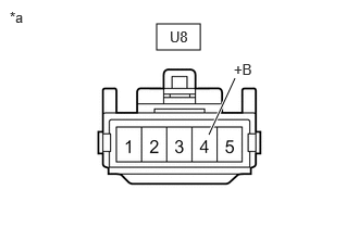
| *a | Front view of wire harness connector
(to Rear Wiper Motor Assembly) |
Measure the voltage according to the value(s) in the table below.
- Standard Voltage:
Tester Connection Switch Condition Specified Condition U8-4 (+B) - Body ground Ignition switch ON 11 to 14 V
- Result:
Proceed to OK NG
OK
4.CHECK HARNESS AND CONNECTOR (REAR WIPER MOTOR ASSEMBLY - BODY GROUND)
NG
REPAIR OR REPLACE HARNESS OR CONNECTOR
4.CHECK HARNESS AND CONNECTOR (REAR WIPER MOTOR ASSEMBLY - BODY GROUND)
a.
Measure the resistance according to the value(s) in the table below.
- Standard Resistance:
Tester Connection Condition Specified Condition U8-5 (E) - Body Ground Always Below 1 Ω
- Result:
Proceed to OK NG
OK
5.CHECK HARNESS AND CONNECTOR (REAR WIPER MOTOR ASSEMBLY - MAIN BODY ECU (MULTIPLEX NETWORK BODY ECU))
NG
REPAIR OR REPLACE HARNESS OR CONNECTOR
5.CHECK HARNESS AND CONNECTOR (REAR WIPER MOTOR ASSEMBLY - MAIN BODY ECU (MULTIPLEX NETWORK BODY ECU))
a.
Disconnect the I85 main body ECU (multiplex network body ECU) connector.
b.
Measure the resistance according to the value(s) in the table below.
- Standard Resistance:
Tester Connection Condition Specified Condition U8-3 (LS) - I85-11 (RWRY) Always Below 1 Ω U8-3 (LS) or I85-11 (RWRY) - Body ground Always 10 kΩ or higher
- Result:
Proceed to OK NG
OK
REPLACE MAIN BODY ECU (MULTIPLEX NETWORK BODY ECU)
NG
REPAIR OR REPLACE HARNESS OR CONNECTOR