DOOR / HATCH POWER BACK DOOR SYSTEM B222731 PBD Unit Pulse Sensor RH Circuit No Signal
DESCRIPTION
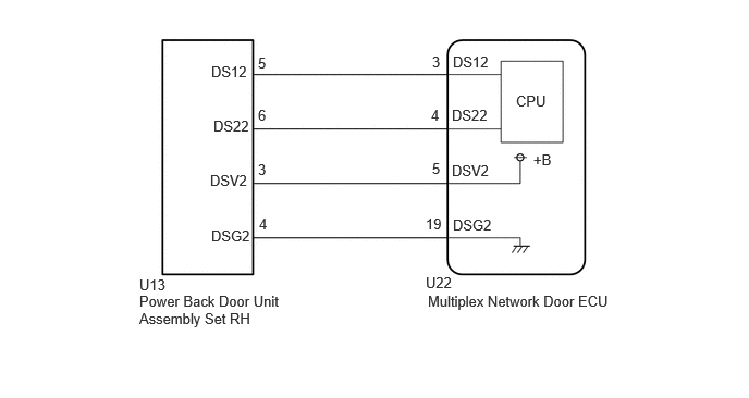
This DTC is output when the multiplex network door ECU detects a power back door unit assembly set RH pulse malfunction.
| DTC No. | Detection Item | DTC Detection Condition | Trouble Area |
|---|---|---|---|
| B222731 | PBD Unit Pulse Sensor RH Circuit No Signal | Multiplex network door ECU detects power back door unit assembly set RH pulse malfunction | ·
Multiplex network door ECU ·
Power back door unit assembly set RH ·
Harness or connector |
WIRING DIAGRAM
CAUTION / NOTICE / HINT
- NOTICE:
-
If the replacement, removal and installation of the multiplex network door ECU or disconnection of the connectors of the multiplex network door ECU has been performed, initialize the power back door system.
PROCEDURE
Clear the DTCs.
- Body Electrical > Back Door > Clear DTCs
- 50002 489
- Result:
Proceed to NEXT
NEXT
Check for DTCs.
- Body Electrical > Back Door > Trouble Codes
- 50001 489
- Result:
Result Proceed to B222731 is output A B222731 is not output B
A
B
Disconnect the U22 multiplex network door ECU connector.
Disconnect the U13 power back door unit assembly set RH connector.
Measure the resistance according to the value(s) in the table below.
- Standard Resistance:
Tester Connection Condition Specified Condition U22-19 (DSG2) - U13-4 (DSG2) Always Below 1 Ω U22-5 (DSV2) - U13-3 (DSV2) Always Below 1 Ω U22-4 (DS22) - U13-6 (DS22) Always Below 1 Ω U22-3 (DS12) - U13-5 (DS12) Always Below 1 Ω U22-19 (DSG2) or U13-4 (DSG2) - Body ground Always 10 kΩ or higher U22-5 (DSV2) or U13-3 (DSV2) - Body ground Always 10 kΩ or higher U22-4 (DS22) or U13-6 (DS22) - Body ground Always 10 kΩ or higher U22-3 (DS12) or U13-5 (DS12) - Body ground Always 10 kΩ or higher
- Result:
Proceed to OK NG
OK
NG
Disconnect the U13 power back door unit assembly set RH connector.
Measure the resistance according to the value(s) in the table below.
- Standard Resistance:
Tester Connection Condition Specified Condition U13-4 (DSG2) - Body ground Always Below 1 Ω
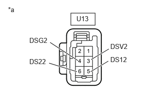
| *a | Front view of wire harness connector
(to Power Back Door Unit Assembly Set RH) |
Measure the voltage according to the value(s) in the table below.
- Standard Voltage:
Tester Connection Condition Specified Condition U13-5 (DS12) - Body ground IG OFF 7 V or higher U13-6 (DS22) - Body ground IG OFF 7 V or higher U13-3 (DSV2) - Body ground IG OFF 7 V or higher
- Result:
Proceed to OK NG
OK
NG
Using an oscilloscope, check the waveform of each terminal from the rear of the U22 multiplex network door ECU connector.
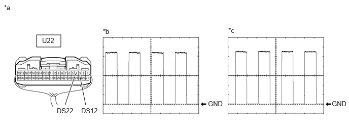
| *a | Component with harness connected
(Multiplex Network Door ECU) |
*b | Waveform (CH1) |
| *c | Waveform (CH2) | - | - |
- Measurement Condition:
Item Condition Tester Connection ·CH1: U22-3 (DS12) - Body ground
·CH2: U22-4 (DS22) - Body ground
Tool setting 2 V/DIV., 2 ms./DIV. Vehicle condition Open and close the back door by hand.
- HINT:
-
The period changes in accordance to the speed at which the back door is opened and closed by hand.
- OK:
The waveform displayed is as shown in the illustration.
- Result:
Proceed to OK NG
OK
NG