DOOR / HATCH POWER BACK DOOR SYSTEM Power Back Door Warning System does not Operate
DESCRIPTION
Depending on the operating conditions, the multiplex network door ECU sounds the buzzer and outputs a hazard light flash signal to the combination meter assembly.
WIRING DIAGRAM
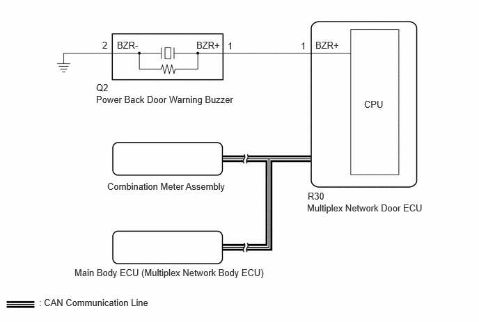
CAUTION / NOTICE / HINT
- NOTICE:
- ·
If the multiplex network door ECU has been replaced, or if any of the connectors has been disconnected, initialize the power back door system.
·First perform the communication function inspections in How to Proceed with Troubleshooting to confirm that there are no CAN communication malfunctions before troubleshooting this problem.
·If the main body ECU (multiplex network body ECU) is replaced, refer to Service Bulletin.
PROCEDURE
Operate the power back door and check that the warning buzzer and hazard warning light operate.
- Result:
Result Proceed to Hazard warning light does not come on A Power back door warning buzzer does not operate B
A
B
Check wireless door lock operation.
w/ Smart Entry and Start System:
w/o Smart Entry and Start System:
- OK:
Hazard answer-back function operates normally.
- Result:
Proceed to OK NG
OK
NG
w/ Smart Entry and Start System:
w/o Smart Entry and Start System:
Temporarily replace the multiplex network door ECU with a new or normally functioning one.
- Result:
Proceed to NEXT
NEXT
Perform the initialization for the multiplex network door ECU.
- Result:
Proceed to NEXT
NEXT
Check that the power back door hazard warning lights operate normally.
- OK:
The power back door hazard warning lights operate normally.
- Result:
Proceed to OK NG
OK
NG
Perform the Active Test according to the display on the GTS.
- Body Electrical > Back Door > Active Test
-
Tester Display Measurement Item Control Range Diagnostic Note PBD Buzzer (Small Volume) Power back door warning buzzer sound (small volume) Start - PBD Buzzer (Middle Volume) Power back door warning buzzer sound (Middle volume) Start - PBD Buzzer (Large Volume) Power back door warning buzzer sound (Large volume) Start -
- Body Electrical > Back Door > Active Test
-
Tester Display PBD Buzzer (Small Volume) - 50004 489 42003
- Body Electrical > Back Door > Active Test
-
Tester Display PBD Buzzer (Middle Volume) - 50004 489 42007
- Body Electrical > Back Door > Active Test
-
Tester Display PBD Buzzer (Large Volume) - 50004 489 42008
- OK:
Power back door warning buzzer sounds.
- Result:
Proceed to OK NG
OK
NG
Disconnect the Q2 Power back door warning buzzer connector.
Perform the Active Test according to the display on the GTS.
- Body Electrical > Back Door > Active Test
-
Tester Display Measurement Item Control Range Diagnostic Note PBD Buzzer (Middle Volume) Power back door warning buzzer sound (Middle volume) Start -
- Body Electrical > Back Door > Active Test
-
Tester Display PBD Buzzer (Middle Volume) - 50004 489 42007
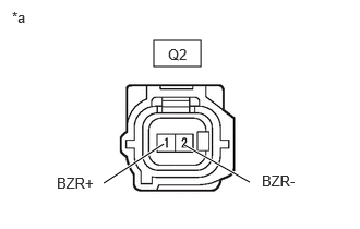
| *a | Front view of wire harness connector
(to Power Back Door Warning Buzzer) |
Measure the voltage according to the value(s) in the table below.
- Standard Voltage:
Tester Connection Condition Specified Condition Q2-1 (BZR+) - Q2-2 (BZR-) Active Test "PBD Buzzer (Middle Volume)" is not performed Below 1 V Active Test "PBD Buzzer (Middle Volume)" is being performed Pulse generation
(frequency: 2 kHz, high voltage: 11 to 14 V, low voltage: below 1 V)
- Result:
Proceed to OK NG
OK
NG
Disconnect the Q2 power back door warning buzzer connector.
Disconnect the R30 multiplex network door ECU connector.
Measure the resistance according to the value(s) in the table below.
- Standard Resistance:
Tester Connection Condition Specified Condition Q2-1 (BZR+) - R30-1 (BZR+) Always Below 1 Ω Q2-2 (BZR-) - Body ground Always Below 1 Ω Q2-1 (BZR+) or R30-1 (BZR+) - Body ground Always 10 kΩ or higher
- Result:
Proceed to OK NG
OK
NG