DOOR / HATCH POWER BACK DOOR SYSTEM Power Back Door does not Operate Using Cabin Switch
DESCRIPTION
The power back door control switch sends a signal to the multiplex network door ECU using CAN communication via the main body ECU (multiplex network body ECU).
WIRING DIAGRAM
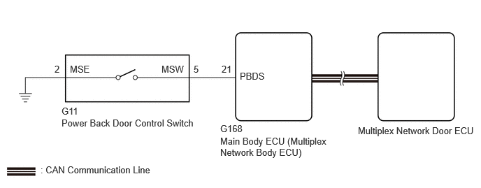
CAUTION / NOTICE / HINT
- NOTICE:
- ·
If the multiplex network door ECU has been replaced, or if any of the connectors has been disconnected, initialize the power back door system.
·First perform the communication function inspections in How to Proceed with Troubleshooting to confirm that there are no CAN communication malfunctions before troubleshooting this problem.
·If the main body ECU (multiplex network body ECU) is replaced, refer to Service Bulletin.
PROCEDURE
Operate the multi-information display and check the customization status.
| Display | Description | Default | Setting | Relevant ECU |
|---|---|---|---|---|
| System Settings | Function that enables or disables the power back door operation. | On | On or Off | Multiplex network door ECU |
- Result:
Result Proceed to Customization item is "On" (power back door system operation is possible) A Customization item is "Off" (power back door system operation is prohibited) B
A
B
Check the power back door system.
- Result:
Result Proceed to Power back door system operates normally A Power back door system does not operate normally B
A
B
Read the Data List according to the display on the GTS.
- Body Electrical > Main Body > Data List
-
Tester Display Measurement Item Range Normal Condition Diagnostic Note Back Door Operation Switch (Instrument) Power back door control switch signal ON or OFF ON: Power back door control switch on
OFF: Power back door control switch off-
- Body Electrical > Main Body > Data List
-
Tester Display Back Door Operation Switch (Instrument) - 50003 449 47
- OK:
The GTS display changes correctly in response to the switch operation.
- Result:
Proceed to OK NG
OK
NG
- Result:
Proceed to OK NG
OK
NG
Disconnect the G11 power back door control switch connector.
Disconnect the G168 main body ECU (multiplex network body ECU) connector.
Measure the resistance according to the value(s) in the table below.
- Standard Resistance:
Tester Connection Condition Specified Condition G11-5 (MSW) - G168-21(PBDS) Always Below 1 Ω G11-2 (MSE) - Body ground Always Below 1 Ω G11-5 (MSW) or G168-21 (PBDS) - Body ground Always 10 kΩ or higher
- Result:
Proceed to OK NG
OK
NG