RM36D0EC _58 Vehicle Interior _083095 LIGHTING (INT) _0400584 LIGHTING SYSTEM J

LIGHTING (INT)  LIGHTING SYSTEM  Interior Light Circuit  


DESCRIPTION

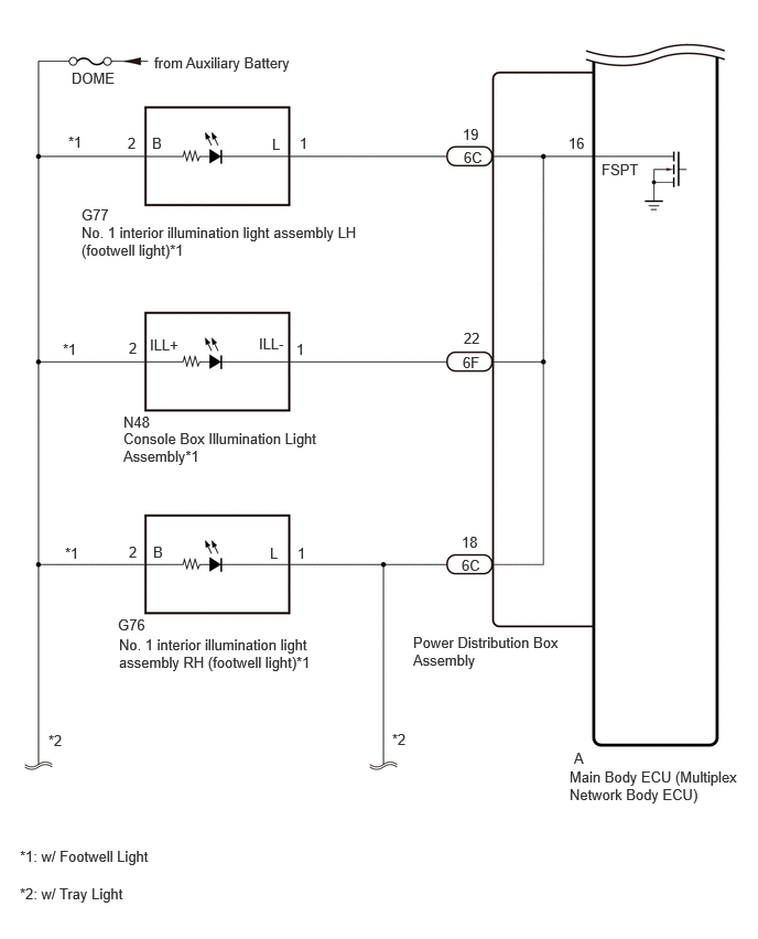
The main body ECU (multiplex network body ECU) controls the operation of the following lights:

·

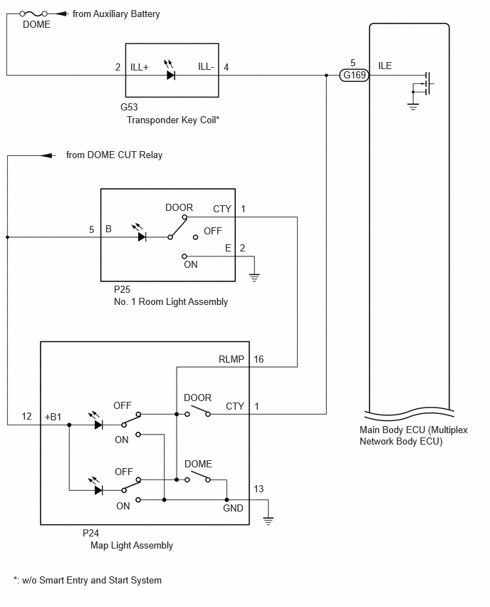
Map light sub-assembly

·

Spot light assembly

·

No. 1 interior illumination light assembly LH (footwell light)*1

·

No. 1 interior illumination light assembly RH (footwell light)*1

·

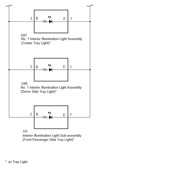
No. 1 interior illumination light assembly (center tray light)*2

·

No. 1 interior illumination light assembly (driver side tray light)*2

·

Interior illumination light sub-assembly (front passenger side tray light)*2

·

Console box illumination light assembly*1

*1: w/ Footwell Light

*2: w/ Tray Light


WIRING DIAGRAM
E546222E01
1.667,4.323 4.573,4.521 2.906,0.198 10 false No. 1 Room Light Assembly 1.063,0.115 4.427,0.313 3.365,0.198 10 false from Auxiliary Battery 0.333,0.271 0.948,0.469 0.615,0.198 10 false DOME 5.531,0.875 5.99,1.073 0.458,0.198 10 false ILE 5.125,0.833 5.281,1.031 0.156,0.198 10 false 5 5.26,6.198 6.906,6.635 1.646,0.438 10 false Main Body ECU (Multiplex Network Body ECU) 1.323,7.885 4.229,8.083 2.906,0.198 10 false Map Light Assembly 1.854,1.667 4.917,1.865 3.063,0.198 10 false Transponder Key Coil* 0.969,2.177 2.813,2.594 1.844,0.417 10 false from DOME CUT Relay 1.76,1.479 2.073,1.677 0.313,0.198 10 false G53 2.896,0.885 3.51,1.083 0.615,0.198 10 false ILL- 1.906,0.896 2.521,1.094 0.615,0.198 10 false ILL+ 1.688,0.896 1.844,1.094 0.156,0.198 10 false 2 3.271,0.896 3.427,1.094 0.156,0.198 10 false 4 1.302,3.271 1.458,3.469 0.156,0.198 10 false 5 1.542,3.26 1.698,3.458 0.156,0.198 10 false B 3.115,2.969 3.573,3.167 0.458,0.198 10 false CTY 3.292,3.542 3.448,3.74 0.156,0.198 10 false E 3.521,2.969 3.677,3.167 0.156,0.198 10 false 1 3.51,3.542 3.667,3.74 0.156,0.198 10 false 2 1.667,4.146 1.979,4.344 0.313,0.198 10 false P25 0.656,6.01 1.115,6.208 0.458,0.198 10 false +B1 0.313,6 0.656,6.344 0.344,0.344 10 false 12 3.302,5.854 3.76,6.052 0.458,0.198 10 false CTY 3.26,7.344 3.719,7.542 0.458,0.198 10 false GND 3.708,7.063 4.458,7.313 0.75,0.25 10 false 13 3.719,5.854 3.875,6.052 0.156,0.198 10 false 1 1.208,7.708 2.344,7.927 1.135,0.219 10 false P24 2.979,3.292 3.438,3.49 0.458,0.198 10 false OFF 1.677,6.813 2.021,7.135 0.344,0.323 10 false OFF 1.656,5.844 2.115,6.042 0.458,0.198 10 false OFF 2.688,5.729 3.146,5.927 0.458,0.198 10 false DOOR 2.417,2.948 2.875,3.146 0.458,0.198 10 false DOOR 2.688,3.781 3,3.979 0.313,0.198 10 false ON 1.677,6.344 1.99,6.542 0.313,0.198 10 false ON 1.698,7.313 2.01,7.51 0.313,0.198 10 false ON 0.198,8.396 3.26,8.594 3.063,0.198 10 false *: w/o Smart Entry and Start System 3.198,5.167 3.656,5.365 0.458,0.198 10 false RLMP 3.708,5.167 4.104,5.385 0.396,0.219 10 false 16 2.698,6.698 3.156,6.896 0.458,0.198 10 false DOME 5.021,1.01 5.479,1.208 0.458,0.198 10 false G169

E442541E12
0.677,0.656 1.292,0.854 0.615,0.198 10 false DOME 1.458,0.51 4.823,0.708 3.365,0.198 10 false from Auxiliary Battery 5.427,7.083 5.583,7.281 0.156,0.198 10 false A 5.385,7.26 7.021,7.646 1.635,0.385 10 false Main Body ECU (Multiplex Network Body ECU) 3.906,5.99 5.333,6.354 1.427,0.365 10 false Power Distribution Box Assembly 0.771,2.115 3.448,2.438 2.677,0.323 10 false No. 1 interior illumination light assembly LH (footwell light)*1 1.125,6.01 2.99,6.375 1.865,0.365 10 false No. 1 interior illumination light assembly RH (footwell light)*1 1.167,4.063 3.031,4.427 1.865,0.365 10 false Console Box Illumination Light Assembly*1 0.188,8.01 2.188,8.281 2,0.271 10 false *1: w/ Footwell Light 5.688,1.521 6.302,1.719 0.615,0.198 10 false FSPT 4.385,1.406 4.698,1.604 0.313,0.198 10 false 6C 4.375,3.344 4.688,3.542 0.313,0.198 10 false 6F 1.438,1.271 1.594,1.469 0.156,0.198 10 false B 1.448,5.135 1.604,5.333 0.156,0.198 10 false B 2.573,1.281 2.729,1.479 0.156,0.198 10 false L 2.552,5.146 2.708,5.344 0.156,0.198 10 false L 1.208,1.271 1.365,1.469 0.156,0.198 10 false 2 1.219,3.208 1.375,3.406 0.156,0.198 10 false 2 1.219,5.135 1.375,5.333 0.156,0.198 10 false 2 2.813,5.146 2.969,5.344 0.156,0.198 10 false 1 2.802,3.219 2.958,3.417 0.156,0.198 10 false 1 2.833,1.271 2.99,1.469 0.156,0.198 10 false 1 4.375,1.188 4.688,1.385 0.313,0.198 10 false 19 4.385,3.115 4.698,3.313 0.313,0.198 10 false 22 5.375,1.271 5.688,1.469 0.313,0.198 10 false 16 0.771,1.948 1.229,2.146 0.458,0.198 10 false G77 1.115,5.823 1.573,6.021 0.458,0.198 10 false G76 1.167,3.906 1.625,4.104 0.458,0.198 10 false N48 1.417,3.177 2.031,3.375 0.615,0.198 10 false ILL+ 2.448,3.167 3.063,3.365 0.615,0.198 10 false ILL- 4.365,5.26 4.677,5.458 0.313,0.198 10 false 6C 4.365,5.042 4.677,5.24 0.313,0.198 10 false 18 0.646,1.26 0.958,1.458 0.313,0.198 10 false *1 0.594,3.219 0.906,3.417 0.313,0.198 10 false *1 0.615,5.146 0.927,5.344 0.313,0.198 10 false *1 0.458,6.917 0.771,7.115 0.313,0.198 10 false *2 3.708,6.906 4.021,7.104 0.313,0.198 10 false *2 0.188,8.365 2.188,8.635 2,0.271 10 false *2: w/ Tray Light

E442542E07
1.219,0.656 1.375,0.854 0.156,0.198 10 false 2 1.438,0.656 1.594,0.854 0.156,0.198 10 false B 2.552,0.667 2.708,0.865 0.156,0.198 10 false E 2.823,0.667 2.979,0.865 0.156,0.198 10 false 1 0.833,1.333 1.292,1.531 0.458,0.198 10 false G87 0.854,1.479 3.375,1.844 2.521,0.365 10 false No. 1 Interior Illumination Light Assembly (Center Tray Light)* 0.208,6.438 2.719,6.75 2.51,0.313 10 false *: w/ Tray Light 1.219,2.604 1.375,2.802 0.156,0.198 10 false 2 1.208,4.521 1.365,4.719 0.156,0.198 10 false 2 2.813,2.615 2.969,2.813 0.156,0.198 10 false 1 2.813,4.531 2.969,4.729 0.156,0.198 10 false 1 1.438,2.615 1.594,2.813 0.156,0.198 10 false B 1.448,4.521 1.604,4.719 0.156,0.198 10 false B 2.542,2.604 2.698,2.802 0.156,0.198 10 false E 2.542,4.552 2.698,4.75 0.156,0.198 10 false E 0.854,3.281 1.313,3.479 0.458,0.198 10 false G86 0.833,3.438 3.333,3.813 2.5,0.375 10 false No. 1 Interior Illumination Light Assembly (Driver Side Tray Light)* 0.927,5.208 1.385,5.406 0.458,0.198 10 false H3 0.906,5.375 3.333,5.76 2.427,0.385 10 false Interior Illumination Light Sub-assembly (Front Passenger Side Tray Light)*

CAUTION / NOTICE / HINT

NOTICE:
·

Inspect the fuses for circuits related to this system before performing the following procedure.

·

If the main body ECU (multiplex network body ECU) is replaced, refer to the Service Bulletin.


PROCEDURE

1.CHECK INTERIOR LIGHT
a.

Check which interior illumination does not turn on.


Result:
Result Proceed to
Map light assembly, No. 1 room light assembly or transponder key coil (w/o Smart Entry and Start System) does not turn on A
No. 1 interior illumination light assembly LH (footwell light) (w/ Footwell Light), No. 1 interior illumination light assembly RH (footwell light) (w/ Footwell Light), Console box illumination light assembly (cup holder light) (w/ Footwell Light), No. 1 interior illumination light assembly (driver side tray light) (w/ Tray Light), interior illumination light sub-assembly (front passenger side tray light) (w/ Tray Light) or No. 1 interior illumination light assembly (center tray light) (w/ Tray Light) does not turn on B


A

2.PERFORM ACTIVE TEST USING GTS

B

4.PERFORM ACTIVE TEST USING GTS
2.PERFORM ACTIVE TEST USING GTS
a.

Perform the Active Test according to the display on the GTS.

Body Electrical > Main Body > Active Test
Tester Display Measurement Item Control Range Diagnostic Note
Illuminated Entry System Turns on the lights that are controlled by the illuminated entry system* OFF or ON Perform the Active Test with the DOOR switch in the map light assembly, No. 1 room light assembly and transponder key coil (w/o Smart Entry and Start System) turned on.
Body Electrical > Main Body > Active Test
Tester Display
Illuminated Entry System
50004 449 20

*: Refer to Operation Check for the lights that are controlled by the illuminated entry system.

Click hereVehicle Interior>LIGHTING (INT)>LIGHTING SYSTEM>OPERATION CHECK


OK:

Map light assembly, No. 1 room light assembly and transponder key coil (w/o Smart Entry and Start System) turn on or off.


Result:
Proceed to
OK
NG


OK

NG

3.CHECK HARNESS AND CONNECTOR (MAP LIGHT SUB-ASSEMBLY - MAIN BODY ECU [MULTIPLEX NETWORK BODY ECU])
a.

Disconnect the P24 map light sub-assembly connector.


b.

Disconnect the P25 No. 1 room light assembly connector.


c.

Disconnect the G53 transponder key coil connector.*

*: w/o Smart Entry and System


d.

Disconnect the G169 main body ECU (multiplex network body ECU) connector.


e.

Measure the resistance according to the value(s) in the table below.

Standard Resistance:
Tester Connection Condition Specified Condition
P24-1 (CTY) - G169-5 (ILE) Always Below 1 Ω
P24-1 (CTY) or G169-5 (ILE) - Body ground Always 10 kΩ or higher


Result:
Proceed to
OK
NG


OK

NG

REPAIR OR REPLACE HARNESS OR CONNECTOR

4.PERFORM ACTIVE TEST USING GTS
a.

Perform the Active Test according to the display on the GTS.

Body Electrical > Main Body > Active Test
Tester Display Measurement Item Control Range Diagnostic Note
Front Footwell Lights Operation of the following lights:
·

No. 1 interior illumination light assembly (driver side footwell light)*

·

No. 2 interior illumination light assembly (front passenger side footwell light)*

·

No. 1 interior illumination light assembly (center tray light)*

·

No. 1 interior illumination light assembly (driver side tray light)*

·

Interior illumination light sub-assembly (front passenger side tray light)*

·

Console box illumination light assembly*


OFF or ON -
Body Electrical > Main Body > Active Test
Tester Display
Front Footwell Lights
50004 449 22

*: w/ Footwell Light


OK:

Connected light is turn on or off.


Result:
Proceed to
OK
NG


OK

NG

5.CHECK HARNESS AND CONNECTOR (NO. 1 INTERIOR ILLUMINATION LIGHT ASSEMBLY [DRIVER SIDE FOOTWELL LIGHT] - POWER DISTRIBUTION BOX ASSEMBLY)

*1: w/ Footwell Light

*2: w/ Tray Light


a.

Disconnect the G77 No. 1 interior illumination light assembly LH (footwell light)*1 connector.


b.

Disconnect the G76 No. 1 interior illumination light assembly RH (footwell light)*1 connector.


c.

Disconnect the G87 No. 1 interior illumination light assembly (center tray light)*2 connector.


d.

Disconnect the G86 No. 1 interior illumination light assembly (driver side tray light)*2 connector.


e.

Disconnect the H3 interior illumination light sub-assembly (front passenger side tray light)*2 connector.


f.

Disconnect the N48 console box illumination light assembly*1 connector.


g.

Disconnect the 6C and 6F power distribution box assembly connectors.


h.

Measure the resistance according to the value(s) in the table below.

Standard Resistance:
Tester Connection Condition Specified Condition
6C-19 - G77-1 (L) Always Below 1 Ω
6C-18 - G76-1 (L) Always Below 1 Ω
6F-22 - N48-1 (ILL-) Always Below 1 Ω
6C-19 or G77-1 (L) - Body ground Always 10 kΩ or higher
6C-18 or G76-1 (L) - Body ground Always 10 kΩ or higher
6F-22 or N48-1 (ILL-) - Body ground Always 10 kΩ or higher


Result:
Proceed to
OK
NG


OK

6.CHECK POWER DISTRIBUTION BOX ASSEMBLY

NG

REPAIR OR REPLACE HARNESS OR CONNECTOR

6.CHECK POWER DISTRIBUTION BOX ASSEMBLY
a.

Remove the power distribution box assembly.
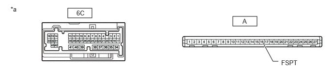
Click herePower Source / Network>POWER DISTRIBUTION>MAIN BODY ECU>REMOVAL

E438211C14
1.458,0.177 1.979,0.385 0.521,0.208 5.01,0.354 5.531,0.563 0.521,0.208 5.99,1.323 5.875,1.323 5.875,1.323 5.656,0.917 true 0.229,0.115 0.542,0.271 0.313,0.156 10 false *a 5.219,0.375 5.375,0.531 0.156,0.156 10 false A 1.646,0.198 1.917,0.385 0.271,0.188 10 false 6C 6.052,1.271 6.594,1.552 0.542,0.281 10 false FSPT
*a Component without harness connected
(Power Distribution Box Assembly)
- -


b.

Remove the main body ECU (multiplex network body ECU) from the power distribution box assembly.

Click herePower Source / Network>POWER DISTRIBUTION>MAIN BODY ECU>REMOVAL


c.

Measure the resistance according to the value(s) in the table below.

Standard Resistance:
Tester Connection Condition Specified Condition
6C-19 - A-16 (FSPT) Always Below 1 Ω


Result:
Proceed to
OK
NG


OK

NG