HEATING / AIR CONDITIONING AIR CONDITIONING SYSTEM(for Gasoline Model) Air Vent Temperature does not Change and Right Vent is Different from Left and Vice Versa (Same Left/Right Temperature Setting)
DESCRIPTION
If there is a difference in temperature between the left and right air outlets while dual mode is ON, the following causes are possible.
| Malfunction Status | Factor |
|---|---|
| There is a difference in temperature between the left and right air outlets (while cooling operation) | ·
Compressor with motor assembly malfunction ·
Lack of refrigerant gas ·
Air mix damper and link operation (jamming) ·
Automatic light control sensor malfunction (for Automatic Air Conditioning System) |
| There is a difference in temperature between the left and right air outlets (while heater operation) | ·
Air mix damper and link operation (jamming) ·
Heater core closed waterway |
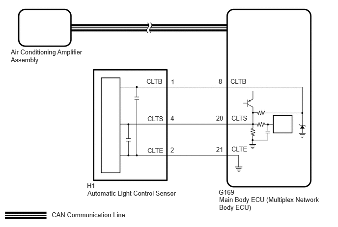
WIRING DIAGRAM
CAUTION / NOTICE / HINT
- NOTICE:
-
If DTC 124400 is output, troubleshoot for DTC 124400 first.
PROCEDURE
- Result:
Result Proceed to While cooling A While heater B
A
B
Prepare the vehicle according to the table below.
| Item | Condition |
|---|---|
| Vehicle Condition | Engine running |
| A/C Switch | On |
| Ambient Temperature*1 | 0 to 49°C (32 to 120°F) |
| Air Conditioning Air Inlet Temperature*2 | 25 to 35°C (77 to 95°F) |
| Set Temperature | MAX COLD |
| Recirculation/fresh Control Switch | Recirculation |
| Air Vent Damper Position | FACE |
| Blower Speed | HI |
- NOTICE:
-
When the GTS is operated without the check conditions satisfied, "Refrigerant incorrect" is displayed. Select "Yes" to return to the previous screen.
- HINT:
- ·
Refer to the GTS operator's manual for further details.
·A message indicating a refrigerant shortage is displayed on the GTS and the air conditioning system turns off if the amount of refrigerant in the system is insufficient.
·DTCs are not stored when performing the refrigerant shortage check using the GTS.
·*1: This inspection can be judged correctly only if the ambient temperature is within a range of 0 to 49°C (32 to 120°F). Therefore, postpone the test if the temperature is low.
·*2: This inspection can be judged correctly only if the air inlet temperature is within a range of 25 to 35°C (77 to 95°F). Therefore, postpone the test if the temperature is out of range.
According to the GTS display, perform refrigerant gas volume check.
- Body Electrical > Air Conditioner > Utility
-
Tester Display Refrigerant Gas Volume Check - 50005 450 4578
- Result:
Result Amount of Refrigerant Refrigerant shortage Insufficient or leakage Refrigerant correct Correct
- OK:
"Refrigerant correct" is displayed on GTS.
- Result:
Proceed to OK NG
OK
NG
Perform the Active Test according to the display on the GTS.
- Body Electrical > Air Conditioner > Active Test
-
Tester Display Measurement Item Control Range Diagnostic Note Front Left Air Mix Damper Control Servo Motor No. 1 air conditioning radiator damper servo sub-assembly operation 128 to 384 Operates between 165 to 257 pulses
(for Automatic Air Conditioning System)Front Right Air Mix Damper Control Servo Motor No. 1 air conditioning radiator damper servo sub-assembly operation 128 to 384 Operates between 255 to 347 pulses
(for Automatic Air Conditioning System)Front Air Outlet Damper Control Servo Motor No. 1 air conditioning radiator damper servo sub-assembly operation 128 to 384 Operates between 165 to 257 pulses
(for Manual Air Conditioning System)
- Body Electrical > Air Conditioner > Active Test
-
Tester Display Front Left Air Mix Damper Control Servo Motor - 50004 450 26
- Body Electrical > Air Conditioner > Active Test
-
Tester Display Front Right Air Mix Damper Control Servo Motor - 50004 450 28
- Body Electrical > Air Conditioner > Active Test
-
Tester Display Front Air Mix Damper Control Servo Motor - 50004 450 46
- OK:
Damper servo motor is operated.
- Result:
Result Proceed to OK (for Automatic Air Conditioning System) A OK (for Manual Air Conditioning System) B NG C
A
B
C
Disconnect the H1 automatic light control sensor connector.
Disconnect the G169 main body ECU (multiplex network body ECU) connector.
Measure the resistance according to the value(s) in the table below.
- Standard Resistance:
Tester Connection Condition Specified Condition H1-1 (CLTB) - G169-8 (CLTB) Always Below 1 Ω H1-2 (CLTE) - G169-21 (CLTE) Always Below 1 Ω H1-4 (CLTS) - G169-20 (CLTS) Always Below 1 Ω H1-1 (CLTB) or G169-8 (CLTB) - Other terminals and body ground Always 10 kΩ or higher H1-2 (CLTE) or G169-21 (CLTE) - Other terminals and body ground Always 10 kΩ or higher H1-4 (CLTS) or G169-20 (CLTS) - Other terminals and body ground Always 10 kΩ or higher
- Result:
Proceed to OK NG
OK
NG
- Result:
Proceed to OK NG
OK
NG
Prepare the vehicle according to the table below.
| Item | Condition |
|---|---|
| Vehicle Condition | Engine running |
| A/C Switch | On |
| Ambient Temperature*1 | 0 to 49°C (32 to 120°F) |
| Air Conditioning Air Inlet Temperature*2 | 25 to 35°C (77 to 95°F) |
| Set Temperature | MAX COLD |
| Recirculation/fresh Control Switch | Recirculation |
| Air Vent Damper Position | FACE |
| Blower Speed | HI |
- NOTICE:
-
When the GTS is operated without the check conditions satisfied, "Refrigerant incorrect" is displayed. Select "Yes" to return to the previous screen.
- HINT:
- ·
Refer to the GTS operator's manual for further details.
·A message indicating a refrigerant shortage is displayed on the GTS and the air conditioning system turns off if the amount of refrigerant in the system is insufficient.
·DTCs are not stored when performing the refrigerant shortage check using the GTS.
·*1: This inspection can be judged correctly only if the ambient temperature is within a range of 0 to 49°C (32 to 120°F). Therefore, postpone the test if the temperature is low.
·*2: This inspection can be judged correctly only if the air inlet temperature is within a range of 25 to 35°C (77 to 95°F). Therefore, postpone the test if the temperature is out of range.
According to the GTS display, perform refrigerant gas volume check.
- Body Electrical > Air Conditioner > Utility
-
Tester Display Refrigerant Gas Volume Check - 50005 450 4578
- Result:
Result Amount of Refrigerant Refrigerant shortage Insufficient or leakage Refrigerant correct Correct
- OK:
"Refrigerant correct" is displayed on GTS.
- Result:
Proceed to OK NG
OK
NG
- Result:
Proceed to NEXT
NEXT
Check that there is not a difference in temperature between the left and right air outlets.
- OK:
There is not a difference in temperature between the left and right air outlets.
- Result:
Proceed to OK NG
OK
NG
Perform the Active Test according to the display on the GTS.
- Body Electrical > Air Conditioner > Active Test
-
Tester Display Measurement Item Control Range Diagnostic Note Front Left Air Mix Damper Control Servo Motor No. 1 air conditioning radiator damper servo sub-assembly operation 128 to 384 Operates between 165 to 257 pulses
(for Automatic Air Conditioning System)Front Right Air Mix Damper Control Servo Motor No. 1 air conditioning radiator damper servo sub-assembly operation 128 to 384 Operates between 255 to 347 pulses
(for Automatic Air Conditioning System)Front Air Mix Damper Control Servo Motor No. 1 air conditioning radiator damper servo sub-assembly operation 128 to 384 Operates between 165 to 257 pulses
(for Manual Air Conditioning System)
- Body Electrical > Air Conditioner > Active Test
-
Tester Display Front Left Air Mix Damper Control Servo Motor - 50004 450 26
- Body Electrical > Air Conditioner > Active Test
-
Tester Display Front Right Air Mix Damper Control Servo Motor - 50004 450 28
- Body Electrical > Air Conditioner > Active Test
-
Tester Display Front Air Mix Damper Control Servo Motor - 50004 450 46
- OK:
Damper servo motor is operated.
- Result:
Proceed to OK NG
OK
NG