HEATING / AIR CONDITIONING AIR CONDITIONING SYSTEM(for Gasoline Model) ON-VEHICLE INSPECTION
PROCEDURE

 1. COOLING PERFORMANCE TEST
Install the air conditioning tool set to the vehicle.
Set the vehicle to the following conditions. [*1]
| Item | Condition |
|---|---|
| Vehicle Body | Vehicle stopped in shade |
| Door | Fully open |
| A/C Switch | ON |
| Fresh/recirculation Mode Control Damper Position | Recirculation |
| Air Vent Damper Position | FACE |
| Set Temperature | MAX COLD |
| Blower Speed | HI |
| Condenser Pressure (Gauge High Pressure Side)*2 | 1.63 to 1.83 MPaG (16.6 to 18.7 kgf/cm2) |
- HINT:
-
*2: If the condenser pressure (gauge high pressure side) is high, splash the condenser with water to lower the pressure. Conversely, if the condenser pressure is low, cover the front of the condenser to raise the pressure.
Place a wet and dry bulb thermometer at the air inlet (necessary for measuring the humidity), and insert its dry bulb at the center of the air vent to measure.
Operate the air conditioning in the conditions of [*1], and allow the temperature at the air vent to stabilize. (Approximately 5 to 6 minutes)
Measure the wet and dry temperatures of the air inlet and the temperature of the air vent.
Map the measurement values of the air inlet to the psychometric diagram to find the relative humidity.
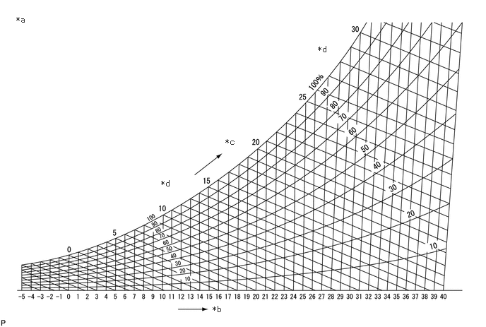
| *a | Psychometric Diagram | *b | Dry Bulb Temperature (°C) |
| *c | Wet Bulb Temperature (°C) | *d | Relative Humidity (%) |
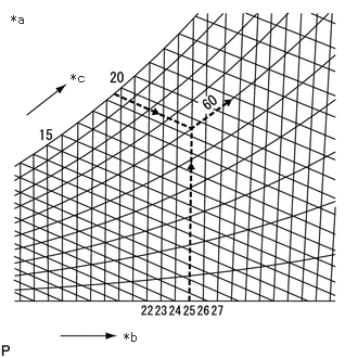
| *a | Example |
| *b | Dry Bulb Temperature (°C) |
| *c | Wet Bulb Temperature (°C) |
One way of finding the relative humidity is to find the intersection point of the wet and dry bulb temperatures, 19.5°C and 25°C, respectively, of the wet and dry bulb thermometer set at the air inlet. In this case, the relative humidity is 60%.
Check the cooling performance by mapping the relative humidity and the difference between the measured dry bulb temperatures of the air inlet and air vent in the standard performance chart.
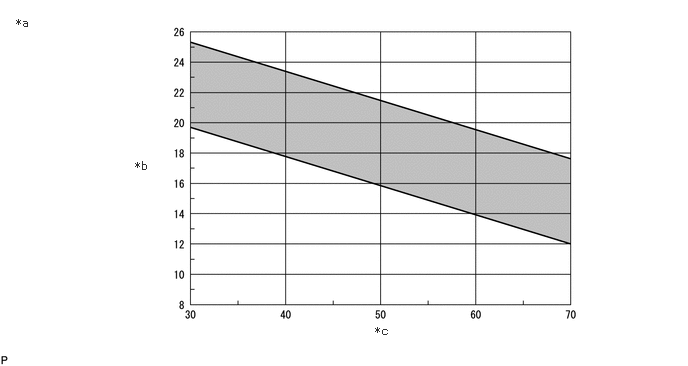
| *a | Standard Performance Chart | *b | Air Inlet/air Vent Temperature Difference (°C) |
| *c | Relative Humidity (%) | - | - |
- Standard:
Must be within the range between the diagonal lines in the chart.
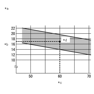
| *a | Example |
| *b | Air inlet/air vent temperature difference (°C) |
| *c | Relative humidity (%) |
| *d | Intersection |
One example of how to check the cooling performance using a standard performance chart is to find the intersection point of the relative humidity (60%) and the difference in dry bulb temperatures at the air inlet and vent (17°C). In this example, the cooling performance is inside the standard range.
2.CHECK REFRIGERANT GAS PRESSURE
Check refrigerant pressure using gauge.
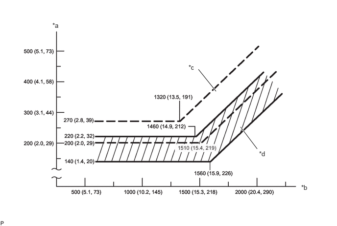
| *a | Pressure on Low Pressure Side kPa (kgf/cm2, psi) | *b | Pressure on High Pressure Side kPa (kgf/cm2, psi) |
| *c | Blower High Zone | *d | Blower Low Zone |
Install the air conditioning tool set.
Set the vehicle to the following conditions. [*3]
| Item | Condition |
|---|---|
| Vehicle Condition | Engine running |
| Door | Fully closed (windows also fully closed) |
| A/C Switch | On |
| Recirculation/fresh Control Switch | Recirculation |
| Set Temperature | MAX COLD |
| Blower Speed | HI |
| Air Conditioning Air Inlet Temperature | 25 to 35°C (77 to 95°F) |
In conditions [*3], read the gauge and check the numerical value.
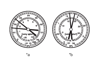
| *a | LO |
| *b | HI |
Normal
- Specified Condition:
Gauge Reading Pressure Side Refrigerant Volume Low 150 to 250 kPa (1.5 to 2.5 kgf/cm2, 22 to 36 psi) High 1630 to 1830 kPa (16.6 to 18.7 kgf/cm2, 236 to 265 psi)
- HINT:
-
The illustration shows the gauges when the refrigerant gas volume is normal.
During malfunction
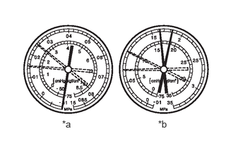
| *a | LO |
| *b | HI |
Symptom 1: During cooling operation, pressure on low pressure side cycles between normal and vacuum.
| Symptom | The air conditioning system works intermittently |
| Cause | Moisture in the cooling system freezes at the cooler expansion valve orifice and temporarily prevents refrigerant gas from circulating. The condition, however, is restored to normal after the ice is melted. |
| Diagnosis | ·
Cooler dryer is overly saturated ·
Moisture in the cooling system freezes at the cooler expansion valve orifice and blocks circulation of the refrigerant gas |
| Action Taken | ·
Replace accumulator assembly ·
Remove moisture from cycle by repeatedly evacuating air ·
Add an appropriate volume of new refrigerant gas |
- HINT:
-
The illustration shows the gauges when moisture has gotten into the cooling system.
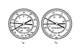
| *a | LO |
| *b | HI |
Symptom 2: The pressure on both the low and high pressure sides is low.
| Symptoms | ·
Cooling is not working well ·
Coolant performance is insufficient |
| Cause | There is a gas leak somewhere in the cooling system |
| Diagnosis | ·
Insufficient refrigerant gas volume ·
Refrigerant gas leak |
| Action Taken | ·
Check for refrigerant gas leak and repair if necessary ·
Add an appropriate volume of new refrigerant gas ·
If the pressure readout value when the gauge is connected is near 0, check for leaking points, make necessary repairs, and then evacuate the air conditioning system |

- HINT:
-
The illustration shows the gauges when cooling is not working well.
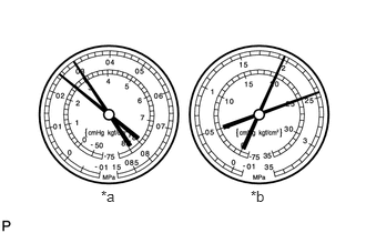
| *a | LO |
| *b | HI |
Symptom 3: The pressure on both the low and high pressure sides is high.
| Symptoms | Cooling is not working well |
| Cause | The flow of refrigerant gas is blocked by moisture or dust in the cooling system |
| Diagnosis | Cooling of cooler condenser core is insufficient |
| Action Taken | ·
Clean the cooler condenser core fin ·
Check the operation of the condenser fan |
- HINT:
-
The illustration shows the gauges when the refrigerant gas volume is excessive or cooling of the cooler condenser core is insufficient.
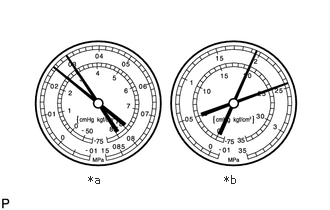
| *a | LO |
| *b | HI |
Symptom 4: The pressure on both the low and high pressure sides is high, and the low pressure line is too hot to touch.
| Symptoms | Cooling is not functioning |
| Cause | Air in refrigeration system |
| Diagnosis | ·
Air is in the refrigeration system ·
Evacuation of the air conditioning system is insufficient |
| Action Taken | ·
Check if the compressor oil is dirty or insufficient ·
Evacuate the air conditioning system, and then add an appropriate volume of new refrigerant gas |
- HINT:
- ·
Notes: The gauge indicates when the cooling system is open without the system being evacuated and filled with refrigerant gas.
·The illustration shows the gauges when air has gotten into the refrigerant system.
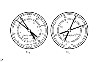
| *a | LO |
| *b | HI |
Symptom 5: The pressure on both the low and high pressure sides is high, and frost or condensation is forming on the low pressure side.
| Symptoms | Cooling is not working well |
| Cause | Trouble with the cooler expansion valve |
| Diagnosis | ·
Refrigerant gas volume is excessive on the low pressure pipe line ·
Cooler expansion valve opened too far |
| Action Taken | ·
Check the air conditioning pressure sensor ·
Check the No. 3 air Conditioning thermistor assembly ·
Check the cooler expansion valve |
- HINT:
-
The illustration shows the gauges when the cooler expansion valve is improper.
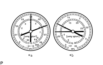
| *a | LO |
| *b | HI |
Symptom 6: The pressure on the low pressure side is high and the pressure on the high pressure side is low.
| Symptoms | Cooling is not functioning |
| Cause | Compression leak inside the compressor with pulley assembly |
| Diagnosis | ·
Compression malfunction ·
Valve leak or damaged sliding parts |
| Action Taken | Repair or replace the compressor with pulley assembly |
- HINT:
-
The illustration shows the gauges when the compression in the compressor with pulley assembly is poor.
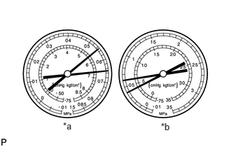
| *a | LO |
| *b | HI |
Symptom 7: The pressure is the same on both the low and high pressure sides.
| Symptoms | Cooling is not functioning |
| Cause | Trouble with the compressor with pulley assembly |
| Diagnosis | Compressor with pulley assembly does not rotate |
| Action Taken | Repair or replace the compressor with pulley assembly |
- HINT:
-
The illustration shows the gauges when the compressor with pulley assembly is malfunctioning.
884A0
3.CHECK COOLER CONDENSER ASSEMBLY
When the fins of the cooler condenser assembly are dirty, clean with water and dry with compressed air.
- NOTICE:
- ·
Do not damage the cooler condenser assembly fins.
·When the cooler condenser assembly fins are bent, use a screwdriver or pliers to straighten them.
4. CHECK FOR REFRIGERANT GAS LEAK
Using a halogen leak detector, check for refrigerant gas leaks from connections on the pipe line.
If refrigerant gas is leaking from a connection on the pipe line, check the tightening torque of the joint.
5. CHECK ECO DRIVE MODE
- HINT:
-
Depending on the environment (condition), the actual control may not change in some situations even if ECO drive mode is activated.
Check that the indicator illuminates and airflow volume from the air outlet is controlled when the integration control and panel assembly (ECO switch) is turned on.
Check that the indicator light turns off and that airflow control is canceled when the integration control and panel assembly (ECO switch) is turned off.