DOOR LOCK WIRELESS DOOR LOCK CONTROL SYSTEM(w/o Smart Entry and Start System) Only Wireless Control Function is Inoperative
DESCRIPTION
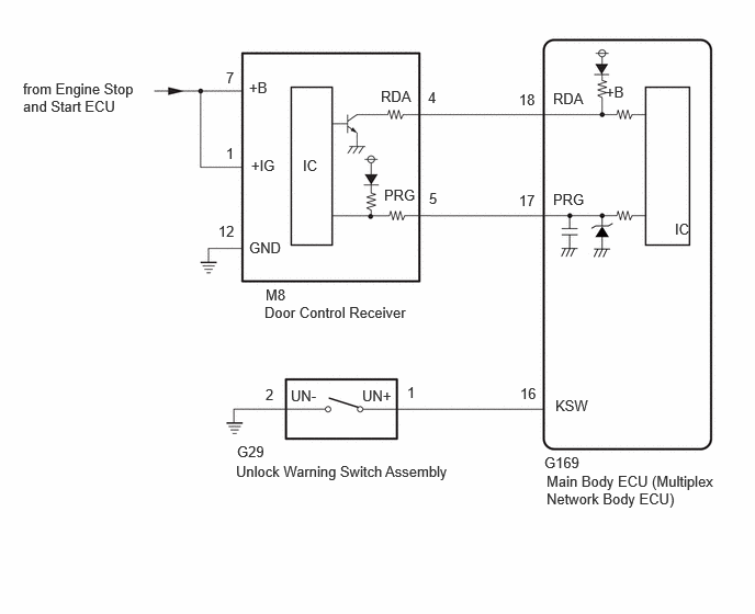
The door control receiver receives signals from the door control transmitter assembly and sends these signals to the main body ECU (multiplex network body ECU). The main body ECU (multiplex network body ECU) then controls all doors by sending lock/unlock signals to each door, and sends hazard flasher signals to the combination meter assembly.
WIRING DIAGRAM
CAUTION / NOTICE / HINT
- NOTICE:
- ·
Inspect the fuses for circuits related to this system before performing the following procedure.
·When replacing or inspecting the door control receiver and wire harness, do not change the position or length of the wire harness. If the wire harness is too close to the door control receiver, wireless function performance may be affected.
·Before replacing the door control transmitter assembly, refer to Service Bulletin.
·If the door control receiver has been replaced, it is necessary to perform initialization (Click hereSuspension>TIRE PRESSURE MONITORING>TIRE PRESSURE WARNING SYSTEM>INITIALIZATION202409,999999,_53,_083075,_0403331,RM100000002NGX2,) after registration (Click here Suspension>TIRE PRESSURE MONITORING>TIRE PRESSURE WARNING SYSTEM>REGISTRATION202409,999999,_53,_083075,_0403331,RM100000002NGX1, ) of the transmitter IDs to the door control receiver assembly.
PROCEDURE
Check the power door lock operation.
- OK:
Locked doors unlock.
- Result:
Proceed to OK NG
OK
NG
Check that the key reminder warning buzzer operates properly.
- OK:
Key reminder warning buzzer operates properly.
- Result:
Proceed to OK NG
OK
NG
When a known good registered door control transmitter assembly is used, check that the wireless functions operate properly.
- Result:
Result Proceed to Wireless door lock/unlock function operates properly with a known good door control transmitter assembly A Wireless door lock/unlock function does not operate B
A
B
Inspect the transmitter battery capacity.
- Result:
Proceed to OK NG
OK
NG
Bring the door control transmitter assembly near the door control receiver, and perform wireless operation check.
- HINT:
- ·
When the door control transmitter assembly is brought near the door control receiver, the possibility of wave interference decreases, and it can be determined if wave interference is causing the problem symptom.
·If the inspection result is that the problem only occurs in certain locations or times of day, the possibility of wave interference is high. Also, added vehicle components may cause wave interference. If installed, remove them and perform the operation check.
- OK:
Wireless functions operate properly.
- Result:
Proceed to OK NG
OK
NG
Disconnect the door control receiver connector.
Measure the voltage according to the value(s) in the table below.
- Standard Voltage:
Tester Connection Switch Condition Specified Condition M8-1 (IG) - Body ground Ignition switch ON 10.5 to 16 V Ignition switch off Below 1 V
- Result:
Proceed to OK NG
OK
NG
Switch to self-diagnostic mode.
Insert the key into the ignition key cylinder and remove it.
Within 5 seconds after the key is removed, insert it into the ignition key cylinder and then turn the ignition switch ON then off 1 time. (End in off)
Within 30 seconds of turning the ignition switch off, perform the following 9 times: Turn the ignition switch ON then off. (End in off)
- HINT:
-
Turning the ignition switch ON after the procedure above has been completed will end the self-diagnostic mode.
- CAUTION:
-
If the system fails to enter the self-diagnostic mode, the system will return to normal mode.
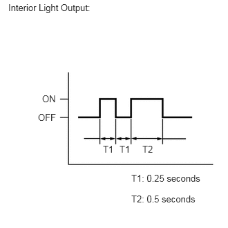
Check that the system has switched to self-diagnostic mode by checking the interior light output pattern.
- Result:
Proceed to NEXT
NEXT
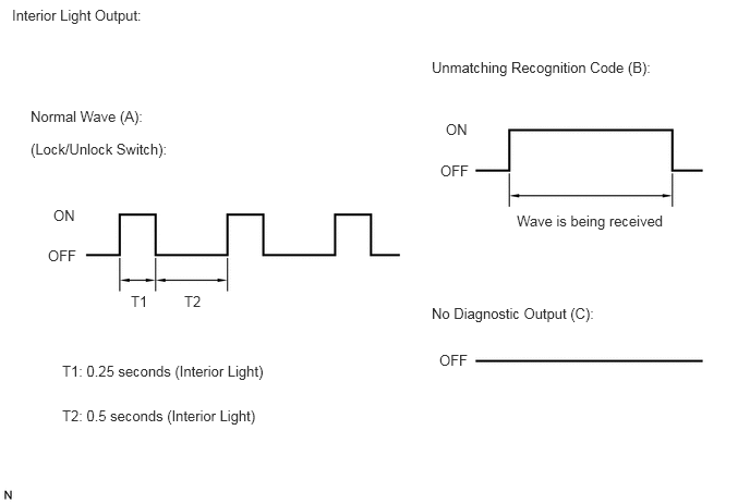
Check the diagnostic outputs when a door control transmitter assembly switch is pressed. The diagnostic outputs can be checked by the interior light patterns.
- Result:
Result Proceed to Normal pattern (interior light output pattern) is output A Unmatching recognition code is output B No diagnostic output C
A
B
C
Check that the system can be switched to rewrite mode or add mode, and that a recognition code can be registered.
- OK:
Recognition code can be registered.
- Result:
Proceed to OK NG
OK
NG
Temporarily replace the door control receiver with a new or known good one.
- Result:
Proceed to NEXT
NEXT
Perform the Registration procedure.
- Result:
Proceed to NEXT
NEXT
Check that the doors can be locked and unlocked by the door control transmitter assembly lock and unlock switches.
- OK:
Doors can be locked and unlocked by the door control transmitter assembly.
- Result:
Proceed to OK NG
OK
NG
Prepare a door control transmitter assembly from another vehicle.
Press and hold a door control transmitter assembly switch.
Check that an unmatching recognition code is output.
- OK:
Unmatching recognition code is output.
- Result:
Proceed to OK NG
OK
NG
Disconnect the M8 door control receiver connector.
Measure the resistance according to the value(s) in the table below.
- Standard Resistance:
Tester Connection Condition Specified Condition M8-12 (GND) - Body ground Always Below 1 Ω
- Result:
Proceed to OK NG
OK
NG
Disconnect the M8 door control receiver connector.
Measure the voltage according to the value(s) in the table below.
- Standard Voltage:
Tester Connection Condition Specified Condition M8-7 (+B) - Body ground Always 10.5 to 16 V
- Result:
Proceed to OK NG
OK
NG
Disconnect the M8 door control receiver connector.
Disconnect the G169 main body ECU (multiplex network body ECU) connector.
Measure the resistance according to the value(s) in the table below.
- Standard Resistance:
Tester Connection Condition Specified Condition M8-4 (RDA) - G169-18 (RDA) Always Below 1 Ω M8-5 (PRG) - G169-17 (PRG) Always Below 1 Ω M8-4 (RDA) or G169-18 (RDA) - Other terminals and body ground Always 10 kΩ or higher M8-5 (PRG) or G169-17 (PRG) - Other terminals and body ground Always 10 kΩ or higher
- Result:
Proceed to OK NG
OK
NG
Disconnect the M8 door control receiver connector.
Measure the voltage according to the value(s) in the table below.
- Standard Voltage:
Tester Connection Condition Specified Condition M8-4 (RDA) - body ground Always 11 to 14 V
- Result:
Proceed to OK NG
OK
NG
Reconnect the M8 door control receiver connector.

| *a | Component with harness connected
(Door Control Receiver) |
Measure the voltage according to the value(s) in the table below.
- Standard Voltage:
Tester Connection Condition Specified Condition M8-4 (RDA) - Body ground Procedure:1.Remove key from ignition key cylinder
2.Close all doors
3.Press lock or unlock switch of door control transmitter assembly
11 to 14 V → pulse generation
- Result:
Proceed to OK NG
OK
NG
Disconnect the G169 main body ECU (multiplex network body ECU) connector.
Measure the voltage according to the value(s) in the table below.
- Standard Voltage:
Tester Connection Condition Specified Condition G45-17 (PRG) - Body ground Always 11 to 14 V
- Result:
Proceed to OK NG
OK
NG