GF2A TRANSFER / 4WD / AWD DYNAMIC TORQUE VECTORING AWD SYSTEM C123A1C Supply Voltage Circuit Circuit Voltage Out of Range
DESCRIPTION
| DTC No. | Detection Item | DTC Detection Condition | Trouble Area | Warning Indicate | Memory |
|---|---|---|---|---|---|
| C123A1C | Supply Voltage Circuit Circuit Voltage Out of Range | ·
The vehicle speed is 3 km/h or higher and the IG1 terminal voltage is below 9.5 V for 10 seconds or more ·
The IG1 terminal voltage is 17 V or higher for 3 seconds or more |
·
Wire harness or connector ·
4WD ECU assembly |
Displayed | Yes |
| Vehicle Condition | |||
|---|---|---|---|
| Pattern 1 | Pattern 2 | ||
| Diagnosis Condition | The vehicle speed is 3 km/h or higher | ○ | - |
| Malfunction Status | The IG1 terminal voltage is below 9.5 V | ○ | - |
| The IG1 terminal voltage is 17 V or higher | - | ○ | |
| Detection Time | 10 seconds or more | 3 seconds or more | |
| Number of Trips | 1 trip | 1 trip | |
- HINT:
-
DTC will be output when conditions for either of the patterns in the table above are met.
WIRING DIAGRAM
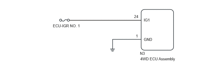
CAUTION / NOTICE / HINT
- NOTICE:
- ·
Inspect the fuses for circuits related to this system before performing the following inspection procedure.
·When the 4WD ECU assembly is replaced, before removing the 4WD ECU assembly, it is necessary to perform ECU Data Save to save the original 4WD ECU assembly information.
·After performing repairs, clear the DTCs and check that the DTCs are not output again.
PROCEDURE
Turn the engine switch off.
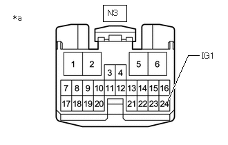
| *a | Front view of wire harness connector
(to 4WD ECU Assembly) |
Disconnect the N3 4WD ECU assembly connector.
Turn the engine switch on (IG).
Measure the voltage according to the value(s) in the table below.
- Standard Voltage:
Tester Connection Condition Specified Condition N3-24 (IG1) - Body ground IG ON 11 to 14 V
- Result:
Proceed to OK NG
OK
NG
Turn the engine switch off.
Disconnect the N3 4WD ECU assembly connector.
Measure the resistance according to the value(s) in the table below.
- Standard Resistance:
Tester Connection Condition Specified Condition N3-1 (GND) - Body ground Always Below 1 Ω
- Result:
Proceed to OK NG
OK
NG