M20C-FKS ENGINE MECHANICAL REAR CRANKSHAFT OIL SEAL REMOVAL
CAUTION / NOTICE / HINT
The necessary procedures (adjustment, calibration, initialization, or registration) that must be performed after parts are removed and installed, or replaced during engine assembly removal/installation are shown below.
| Replaced Part or Performed Procedure | Necessary Procedure | Effect/Inoperative Function when Necessary Procedure not Performed | Link |
|---|---|---|---|
| Replacement of ECM | Perform Vehicle Identification Number (VIN) or frame number registration | DTC P063051 is output | ( 202304,999999,_51,_087036,_0418131,RM1000000029CMS,) 202304,999999,_51,_087036,_0418131,RM1000000029CMS,)
|
| Perform Total Short Trip Estimate Registration | - | ||
GPF Deposition Values:
·
GPF deposition values save ·
GPF deposition values write |
·
MIL comes on ·
Deterioration of fuel efficiency |
||
| Update ECU security key | Vehicle Control History (RoB) are stored | (202405,999999,_V1,_083041,_0402305,RM100000002ISNL,)
|
|
| ECU communication ID registration | Engine start function | See Service Bulletin for the registration method. | |
| Replacement of ECM | for K121:
If transaxle compensation code read from ECM -
Transfer transaxle compensation code -
Deceleration sensor zero point calibration -
CVT oil pressure calibration -
Perform road test to allow ECM to learn |
·
Large shift shock ·
Deterioration of fuel efficiency |
for Initialization:
( 202405,202409,_52,_138176,_0584691,RM100000002JGMX,202409,999999,_52,_138176,_0584691,RM100000002NRHB,)
for Registration: ( 202304,999999,_52,_138176,_0584691,RM1000000029HF6,)
|
for K121:
If transaxle compensation code not read from ECM -
Reset transaxle compensation code -
Deceleration sensor zero point calibration -
CVT oil pressure calibration -
Perform road test to allow ECM to learn |
|||
| Replacement of ECM | for K121F:
If transaxle compensation code read from ECM -
Transfer transaxle compensation code -
Deceleration sensor zero point calibration -
CVT oil pressure calibration -
Perform road test to allow ECM to learn |
·
Large shift shock ·
Deterioration of fuel efficiency |
for Initialization:
( 202405,202409,_52,_138817,_0596468,RM100000002JJ5Q,202409,999999,_52,_138817,_0596468,RM100000002NRBH,)
for Registration: ( 202304,999999,_52,_138817,_0596468,RM100000002AWR8,)
|
for K121F:
If transaxle compensation code not read from ECM -
Reset transaxle compensation code -
Deceleration sensor zero point calibration -
CVT oil pressure calibration -
Perform road test to allow ECM to learn |
|||
| Exhaust manifold | Reset total short trip estimate | ·
MIL comes on ·
Deterioration of fuel efficiency |
(202405,999999,_51,_087036,_0418131,RM100000002IF8T,)
|
| Replacement of front exhaust pipe assembly | GPF deposition value clear | ·
MIL comes on ·
Deterioration of fuel efficiency |
(202405,999999,_51,_087036,_0418131,RM100000002IF8T,)
|
·
Replacement of engine assembly ·
Gas leak from exhaust system is repaired |
Inspection after repair | ·
Poor idle, etc. ·
Engine start function, etc. |
(202405,999999,_51,_087036,_0418131,RM100000002IF8T,)
|
for K121:
Replacement of continuously variable transaxle assembly |
Air bleed oil pump with motor assembly | Stop and start system | (202405,202409,_51,_083056,_0694819,RM100000002LU7O,202409,999999,_51,_083056,_0402418,RM100000002NSFT,)
|
·
Input transaxle compensation code into ECM ·
Perform reset memory ·
Deceleration sensor zero point calibration ·
CVT oil pressure calibration ·
Perform road test to allow ECM to learn |
·
Large shift shock ·
Deterioration of fuel efficiency |
for Initialization:
( 202405,202409,_52,_138176,_0584691,RM100000002JGMX,202409,999999,_52,_138176,_0584691,RM100000002NRHB,)
for Registration: ( 202304,999999,_52,_138176,_0584691,RM1000000029HF6,)
|
|
for K121F:
Replacement of continuously variable transaxle assembly |
Air bleed oil pump with motor assembly | Stop and start system | (202405,202409,_51,_083056,_0694819,RM100000002LU7O,202409,999999,_51,_083056,_0402418,RM100000002NSFT,)
|
·
Input transaxle compensation code into ECM ·
Perform reset memory ·
Deceleration sensor zero point calibration ·
CVT oil pressure calibration ·
Perform road test to allow ECM to learn |
·
Large shift shock ·
Deterioration of fuel efficiency |
for Initialization:
( 202405,202409,_52,_138817,_0596468,RM100000002JJ5Q,202409,999999,_52,_138817,_0596468,RM100000002NRBH,)
for Registration: ( 202304,999999,_52,_138817,_0596468,RM100000002AWR8,)
|
|
| CVT fluid | ATF thermal degradation estimate reset | The value of the Data List item "ATF Thermal Degradation Estimate" is not estimated correctly | for K121:
( 202405,202409,_52,_138176,_0584691,RM100000002JGMX,202409,999999,_52,_138176,_0584691,RM100000002NRHB,)
for K121F: ( 202405,202409,_52,_138817,_0596468,RM100000002JJ5Q,202409,999999,_52,_138817,_0596468,RM100000002NRBH,)
|
| Air bleed oil pump with motor assembly | Stop and start system | (202405,202409,_51,_083056,_0694819,RM100000002LU7O,202409,999999,_51,_083056,_0402418,RM100000002NSFT,)
|
|
| Front bumper assembly (Including removal and installation) | Front television camera view adjustment | Panoramic view monitor system | (202304,999999,_56,_083082,_0586733,RM1000000029R9F,)
|
| Suspension, tires, etc. | Parking assist ECU initialization | Panoramic view monitor system | (202304,999999,_56,_083082,_0586733,RM1000000029R9F,)
|
| Front wheel alignment adjustment | 1.
Perform "Reset Memory". 2.
Perform acceleration sensor zero point calibration and store system information memorization. |
·
VSC is disabled or malfunctions ·
DTCs are output ·
Slip indicator light illuminates ·
ABS warning light illuminates |
(202304,999999,_54,_083077,_0402316,RM100000002AG8P,)
|
- HINT:
-
When the cable is disconnected / reconnected to the auxiliary battery terminal, systems temporarily stop operating. However, each system has a function that completes learning the first time the system is used.
- ·
Learning completes when vehicle is driven
Effect/Inoperative Function When Necessary Procedures are not Performed Necessary Procedures Link Stop and start system Drive the vehicle until stop and start control is permitted (approximately 5 to 60 minutes). ( 202405,202409,_51,_083056,_0694819,RM100000002LU7I,202409,999999,_51,_083056,_0402418,RM100000002NSFO,)
Lane tracing assist system Drive the vehicle straight ahead at 15 km/h (10 mph) or more for 1 second or more. ( 201910,999999,_58,_083101,_0401880,RM100000001JE9I,)
Pre-collision system
·Learning completes when vehicle is operated normally
Effect/Inoperative Function When Necessary Procedures are not Performed Necessary Procedures Link *: w/ Power back door system
Power back door function* Fully close the back door by hand.
- HINT:
-
Initialization is not necessary if the above procedures are performed while the back door is closed.
( 202304,999999,_59,_083093,_0584672,RM1000000029PGT,)
Power door lock control system If the back door is locked and therefore cannot be opened, it is necessary to unlock the back door using the door control switch, electrical key transmitter sub-assembly switch. ( 202405,202409,_58,_083092,_0694211,RM100000002LR98,202409,999999,_58,_083092,_0403003,RM100000002NS90,)
Air conditioning system After the ignition switch is turned to ON, the servo motor standard position is recognized -
- NOTICE:
-
This procedure includes the removal of small-head bolts. Refer to Small-Head Bolts of Basic Repair Hint to identify the small-head bolts.
PROCEDURE

 30400
1.REMOVE CONTINUOUSLY VARIABLE TRANSAXLE ASSEMBLY
30400
1.REMOVE CONTINUOUSLY VARIABLE TRANSAXLE ASSEMBLY
32101B
2.REMOVE DRIVE PLATE AND RING GEAR SUB-ASSEMBLY
Using height adjustment attachments and plate lift attachments, place the engine assembly on a flat level surface.
- NOTICE:
- ·
Using height adjustment attachments and plate lift attachments, keep the engine assembly level.
·To prevent the No. 2 oil pan sub-assembly from deforming, do not place any attachments under the No. 2 oil pan sub-assembly of the engine assembly.
·Using an engine sling device and engine lift, secure the engine assembly before servicing.
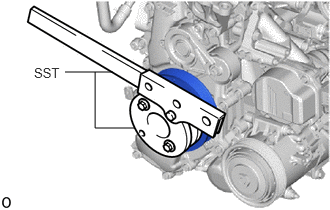
Using SST, hold the crankshaft pulley assembly.
- SST
- 09213-54015
09330-00021
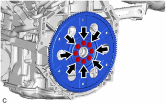
Remove the 8 bolts, rear drive plate spacer, drive plate and ring gear sub-assembly.
19315
3.REMOVE NO. 1 CRANKSHAFT POSITION SENSOR PLATE
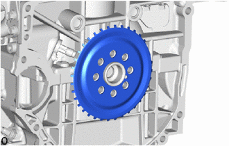
Remove the No. 1 crankshaft position sensor plate.
11401L
4.REMOVE REAR ENGINE OIL SEAL

| *a | Protective Tape |
| *b | Cut Position |
Using a knife, cut off the lip of the rear engine oil seal.
Using a screwdriver, pry out the rear engine oil seal.
- NOTICE:
-
Do not damage the surface of the rear engine oil seal press fit hole or the crankshaft.
- HINT:
-
Tape the screwdriver tip before use.