K121F CVT CONTINUOUSLY VARIABLE TRANSAXLE ASSEMBLY REMOVAL
CAUTION / NOTICE / HINT
The necessary procedures (adjustment, calibration, initialization, or registration) that must be performed after parts are removed, installed, or replaced during the continuously variable transaxle assembly removal/installation are shown below.
| Replacement Part or Procedure | Necessary Procedure | Effect/Inoperative when not Performed | Link |
|---|---|---|---|
| Continuously variable transaxle assembly | Air bleed oil pump with motor assembly | Stop and start system | ( 202409,999999,_51,_083056,_0402418,RM100000002NSFT,) 202409,999999,_51,_083056,_0402418,RM100000002NSFT,)
|
·
Input transaxle compensation code into ECM ·
Perform reset memory ·
Deceleration sensor zero point calibration ·
CVT oil pressure calibration ·
Perform road test to allow ECM to learn |
·
Large shift shock ·
Deterioration of fuel efficiency |
for Initialization:
( 202409,999999,_52,_138817,_0596468,RM100000002NRBH,)
for Registration: ( 202304,999999,_52,_138817,_0596468,RM100000002AWR8,)
|
|
| CVT fluid | ATF thermal degradation estimate reset | The value of the Data List item "ATF Thermal Degradation Estimate" is not estimated correctly | (202409,999999,_52,_138817,_0596468,RM100000002NRBH,)
|
| Air bleed oil pump with motor assembly | Stop and start system | (202409,999999,_51,_083056,_0402418,RM100000002NSFT,)
|
|
| Front wheel alignment adjustment | 1.
Perform "Reset Memory". 2.
Perform acceleration sensor zero point calibration and store system information memorization. |
·
VSC is disabled or malfunctions ·
DTCs are output ·
Slip indicator light illuminates ·
ABS warning light illuminates |
(202304,999999,_54,_083077,_0402316,RM100000002AG8P,)
|
| Front bumper assembly (Including removal and installation) | Front television camera view adjustment | Panoramic view monitor system (for Gasoline model) | (202304,999999,_56,_083082,_0586733,RM1000000029R9F,)
|
| Suspension, tires, etc. | Parking assist ECU initialization |
- CAUTION:
- ·
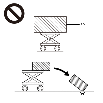 2.219,0.813 2.646,0.813 false 2.698,0.729 3.01,0.927 0.313,0.198 10 false *a
*a An Object Exceeding Weight Limit of Engine Lifter
The engine assembly with transaxle is very heavy. Be sure to follow the procedure described in the repair manual, or the engine lifter may suddenly drop or the engine assembly with transaxle may fall off the engine lifter.
·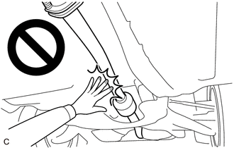
When the engine is hot, do not touch high-temperature areas such as the engine or exhaust pipe.
·Touching high-temperature areas such as the engine and exhaust pipe could result in burns.
- HINT:
-
When the cable is disconnected / reconnected to the auxiliary battery terminal, systems temporarily stop operating. However, each system has a function that completes learning the first time the system is used.
- ·
Learning completes when vehicle is driven
Effect/Inoperative Function When Necessary Procedures are not Performed Necessary Procedures Link Stop and start system Drive the vehicle until stop and start control is permitted (approximately 5 to 60 minutes). ( 202409,999999,_51,_083056,_0402418,RM100000002NSFO,)
Lane tracing assist system Drive the vehicle straight ahead at 15 km/h (10 mph) or more for 1 second or more. ( 201910,999999,_58,_083101,_0401880,RM100000001JE9I,)
Pre-collision system
·Learning completes when vehicle is operated normally
Effect/Inoperative Function When Necessary Procedures are not Performed Necessary Procedures Link *: w/ Power back door system
Power back door function* Fully close the back door by hand.
- HINT:
-
Initialization is not necessary if the above procedures are performed while the back door is closed.
( 202304,999999,_59,_083093,_0584672,RM1000000029PGT,)
Power door lock control system If the back door is locked and therefore cannot be opened, it is necessary to unlock the back door using the door control switch, electrical key transmitter sub-assembly switch. ( 202409,999999,_58,_083092,_0403003,RM100000002NS90,)
Air conditioning system After the ignition switch is turned to ON, the servo motor standard position is recognized -
PROCEDURE

 1.REMOVE ENGINE ASSEMBLY WITH TRANSAXLE
17141
2.REMOVE EXHAUST MANIFOLD
11361J
3.REMOVE FLYWHEEL HOUSING UNDER COVER
32101G
4.REMOVE DRIVE PLATE AND TORQUE CONVERTER SETTING BOLT
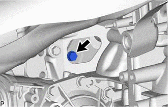
Turn the crankshaft to gain access to the 6 drive plate and torque converter setting bolts and remove each drive plate and torque converter setting bolt while holding the crankshaft pulley bolt with a wrench.
- HINT:
-
There will be one black colored drive plate and torque converter setting bolt.
23825A
5.REMOVE FUEL DELIVERY GUARD
6.INSTALL ENGINE HANGERS
45319
7.REMOVE STEERING GEAR HEAT INSULATOR
8.DISCONNECT WIRE HARNESS
51100H
9.REMOVE FRONT ENGINE SUPPORT MEMBER SUB-ASSEMBLY
82121
10.DISCONNECT ENGINE WIRE
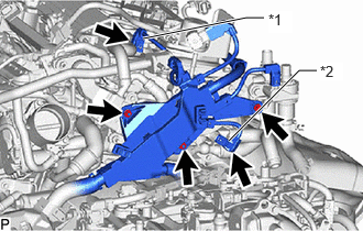
| *1 | Camshaft Position Sensor Connector |
| *2 | Engine Coolant Temperature Sensor Connector |
Remove the bolt and 2 nuts to disconnect the engine wire from the engine assembly.
Disconnect the camshaft position sensor connector.
Disconnect the engine coolant temperature sensor connector.
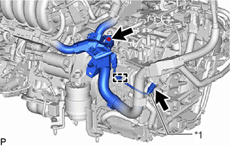
| *1 | Flow Shutting Valve (Water Valve) Connector |
Disconnect the flow shutting valve (water valve) connector.
Remove the bolt to disconnect the engine wire from the continuously variable transaxle assembly.
Detach the clamp to disconnect the engine wire.
Detach the claw, rotate the lever and disconnect the transmission wire connector.
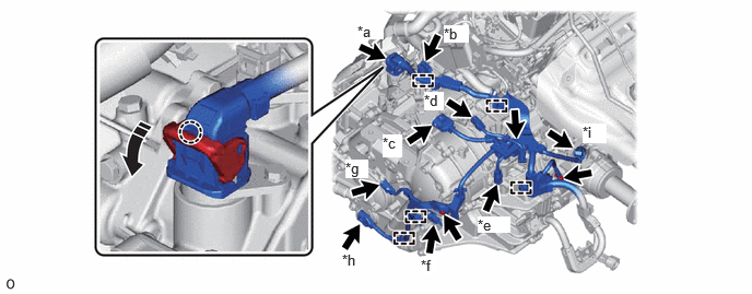
| *a | Transmission Wire Connector | *b | Shift Stroke Sensor Connector |
| *c | Shift Lever Position Sensor Connector | *d | Transmission Revolution Sensor (NOUT) Connector |
| *e | Transmission Revolution Sensor (NSS) Connector | *f | Oil Pressure Sensor Connector |
| *g | Transmission Revolution Sensor (NT) Connector | *h | Oil Pump With Motor Assembly Connector |
| *i | Transfer Sensor Connector | - | - |

|
Remove in this Direction | - | - |
Disconnect the shift stroke sensor connector.
Disconnect the shift lever position sensor connector.
Disconnect the transmission revolution sensor (NOUT) connector.
Disconnect the transmission revolution sensor (NSS) connector.
Disconnect the oil pressure sensor connector.
Disconnect the transmission revolution sensor (NT) connector.
Disconnect the oil pump with motor assembly connector.
for Transfer (GF2A):
Disconnect the transfer sensor connector.
Remove the 3 bolts to disconnect the engine wire from the continuously variable transaxle assembly.
Detach the 5 clamps to disconnect the engine wire.
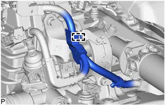
Detach the clamp to disconnect the engine wire.
16261G
11.DISCONNECT NO. 1 WATER BY-PASS HOSE
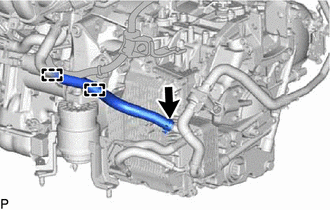
Slide the hose clip and disconnect the No. 1 water by-pass hose from the transmission oil cooler.
Detach the 2 clamps.
16264D
12.REMOVE NO. 2 WATER BY-PASS HOSE
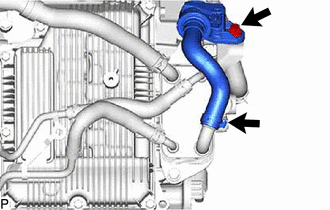
Slide the hose clip and disconnect the No. 2 water by-pass hose from the transmission oil cooler.
Remove the bolt and No. 2 water by-pass hose from the water hose clamp bracket.
13.REMOVE WATER BY-PASS PIPE SUB-ASSEMBLY
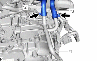
| *1 | Water By-pass Pipe Sub-assembly |
| *2 | No. 3 Water By-pass Hose |
| *3 | No. 4 Water By-pass Hose |
Slide the 2 hose clips and disconnect the No. 3 water by-pass hose and No. 4 water by-pass hose from the water by-pass pipe sub-assembly.
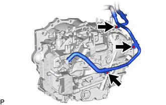
Remove the 3 bolts and water by-pass pipe sub-assembly from the continuously variable transaxle assembly.
32942N
14.DISCONNECT NO. 1 OIL COOLER OUTLET HOSE
32941R
15.DISCONNECT OIL COOLER INLET HOSE
33493C
16.REMOVE TRANSMISSION OIL COOLER
37117
17.REMOVE PROPELLER SHAFT HEAT INSULATOR
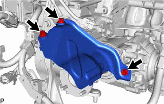
Remove the 3 bolts and propeller shaft heat insulator from the manual transaxle assembly.
12361
18.REMOVE FRONT ENGINE MOUNTING INSULATOR
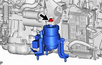
Remove the bolt and front engine mounting bracket from the transverse engine engine mounting insulator.
12311A
19.REMOVE TRANSVERSE ENGINE ENGINE MOUNTING BRACKET
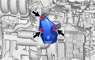
Remove the 3 bolts and transverse engine engine mounting bracket from the continuously variable transaxle assembly.
28100
20.REMOVE STARTER ASSEMBLY
11363A
21.REMOVE FLYWHEEL HOUSING SIDE COVER
12371A
22.REMOVE REAR ENGINE MOUNTING INSULATOR
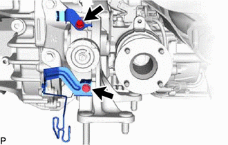
Remove the 2 bolts and 2 wire harness clamp brackets from the rear engine mounting insulator.
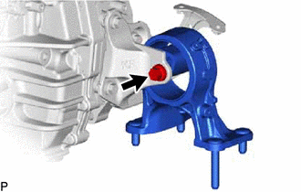
Remove the bolt and rear engine mounting insulator from the rear engine mounting bracket sub-assembly.
12303
23.REMOVE REAR ENGINE MOUNTING BRACKET SUB-ASSEMBLY
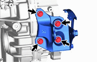
Remove the 4 bolts and rear engine mounting bracket sub-assembly from the continuously variable transaxle assembly.
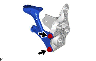
Remove the 2 bolts and No. 2 rear engine mounting bracket from the rear engine mounting bracket.
30400
24.REMOVE CONTINUOUSLY VARIABLE TRANSAXLE ASSEMBLY

|
Bolt A |

|
Bolt B |

|
Bolt C |
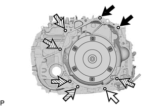
Remove the 8 bolts and continuously variable transaxle assembly from the engine assembly.
- NOTICE:
-
To prevent damage to the 2 knock pins, do not pry between the continuously variable transaxle assembly and engine assembly.
- HINT:
- ·
Bolt (A), (B): Remove from continuously variable transaxle assembly side.
·Bolt (C): Remove from engine assembly side.
32000A
25.REMOVE TORQUE CONVERTER ASSEMBLY
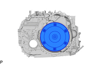
Remove the torque converter assembly from the continuously variable transaxle assembly.
- NOTICE:
-
Remove the torque converter assembly from the input shaft horizontally.
26.REMOVE TRANSAXLE HOUSING TYPE T OIL SEAL
- NOTICE:
- ·
Do not remove the stator shaft assembly from the CVT main body as there is a possibly of the entry of dust and foreign matter.
·Clean the work area, the tools to be used, and other equipment, etc. thoroughly before the operation, as there is the possibility that a CVT malfunction, which could prevent the vehicle from being able to be driven, could occur if dust or fine foreign matter enters the CVT.
·Do not use cotton work gloves, cloths, or paper towels, etc. that may produce lint, dust or foreign matter.
·Perform the operation as quickly as possible, as dust and foreign matter could enter the CVT while the torque converter assembly is removed.
·Do not use an air gun until the torque converter assembly has been installed, as it could cause dust and foreign matter to be stirred up.
Clean the tips of both the claws of SST and the center bolt.
- SST
- 09308-10010
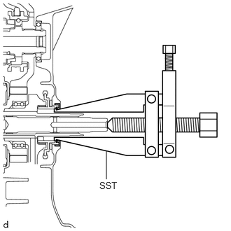
Using SST, remove the transaxle housing type T oil seal.
- NOTICE:
-
Pay attention to the angle of the claws when opening them, and ensure that they do not come into contact with the oil pump housing, as there is the possibility that metal particles could be produced if they do.
12304
27.REMOVE ENGINE MOUNTING BRACKET SUB-ASSEMBLY LH
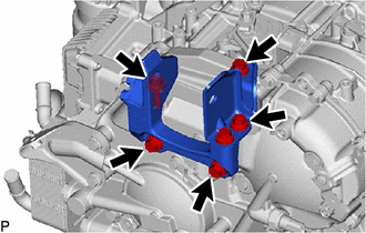
Remove the 5 bolts and engine mounting bracket sub-assembly LH from the continuously variable transaxle assembly.
28.REMOVE WIRE HARNESS CLAMP BRACKET
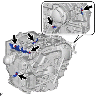
Remove the 6 bolts and 5 wire harness clamp brackets from the continuously variable transaxle assembly.
16575B
29.REMOVE NO. 2 WATER HOSE CLAMP BRACKET
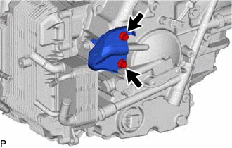
Remove the 2 bolts and No. 2 water hose clamp bracket from the continuously variable transaxle assembly.
33823
30.REMOVE NO. 1 TRANSMISSION CONTROL CABLE BRACKET
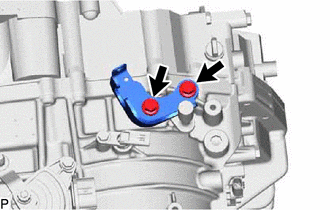
Remove the 2 bolts and No. 1 transmission control cable bracket from the continuously variable transaxle assembly.
35150B
31.REMOVE TRANSMISSION CASE PLUG ASSEMBLY
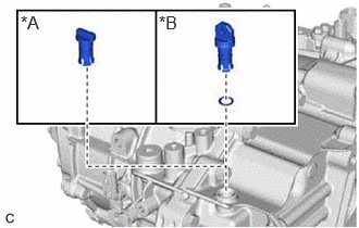
| *A | for Type A |
| *B | for Type B |
for Type A:
Remove the transmission case plug assembly from the continuously variable transaxle assembly.
for Type B:
Remove the transmission case plug assembly from the continuously variable transaxle assembly.
Remove the O-ring from the transmission case plug assembly.
32.REMOVE BREATHER PLUG SUB-ASSEMBLY
- HINT:
-
Perform this procedure only when replacement of the breather plug sub-assembly is necessary.
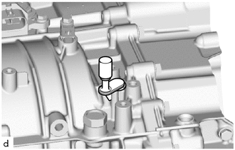
Remove the breather plug sub-assembly from the continuously variable transaxle assembly.
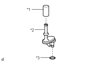
| *1 | Breather Plug Cap |
| *2 | Breather Plug |
| *3 | O-ring |
Remove the breather plug cap from the breather plug.
Remove the O-ring from the breather plug.
36100
33.REMOVE TRANSFER ASSEMBLY
36100A
34.REMOVE TRANSFER AND TRANSAXLE SETTING STUD BOLT
- HINT:
-
It is not necessary to remove the transfer and transaxle setting stud bolts unless they are being replaced.
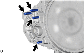
for Continuously Variable Transaxle Assembly Side:
Remove the 4 transfer and transaxle setting stud bolts.
for Transfer Side:
32000A
35.INSPECT TORQUE CONVERTER ASSEMBLY
32101B
36.INSPECT DRIVE PLATE AND RING GEAR SUB-ASSEMBLY