GF2A TRANSFER / 4WD / AWD DYNAMIC TORQUE VECTORING AWD SYSTEM PRECAUTION
TROUBLESHOOTING PRECAUTION
- NOTICE:
- ·
Since the Dynamic Torque Vectoring AWD system may be influenced by a malfunction in other systems, be sure to check for DTCs in the other systems.
·After performing repairs, clear the DTCs and check that the DTCs are not output again.
·Replace the 4WD ECU assembly with a new one.
·When the 4WD ECU assembly is replaced, before removing the 4WD ECU assembly, it is necessary to perform ECU Data Save to save the original 4WD ECU assembly information.
·When the 4WD ECU assembly is replaced, it is necessary to perform the following inorder: ECU Data Initialization and ECU Data Write.
·When the rear 4WD linear solenoid (electro magnetic control coupling sub-assembly) isreplaced, it is necessary to perform the following in order: ECU Data Initialization andECU Data Write (when replacing rear 4WD linear solenoid (electro magnetic controlcoupling sub-assembly)).
·When the front 4WD linear solenoid (transfer assembly) or rear 4WD linear solenoid (rear differential carrier assembly) is replaced, it is necessary to perform the followingin order: ECU Data Initialization and Disconnect System Function Check.
·When the yaw rate and acceleration sensor (airbag ECU assembly) is replaced, it isnecessary to perform ECU Data Initialization.
AWD CONTROL PREVENTION MODE PROCEDURES FOR INSPECTION AND MAINTENANCE
When using speedometer tester
- NOTICE:
- ·
Testers with a load setting mechanism for 2 wheels only (models with a power absorption mechanism for 2 wheels only: 2-wheel chassis dynamometer, or any combination testers such as 2-wheel chassis dynamometer with speedometer tester or brake tester) cannot be used by themselves.
·Perform the inspection on the front wheels.
·Do not start off, accelerate or decelerate suddenly.
·The vehicle speed should be 60 km/h or less. (When a free roller is in use, the vehicle speed should be 50 km/h or less)
·The driving time should be within 1 minute.
Disconnect the 4WD ECU assembly connector and set the system to the AWD control operation prohibited condition.
Drive the vehicle and check that no AWD control operation status display graduations are displayed on the multi-information display for any wheel.
Place the front wheels onto the roller.
Place the rear wheels onto the free roller or safety stand.
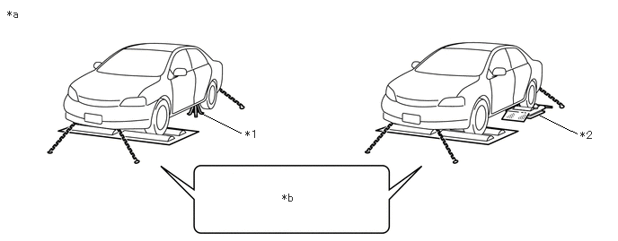
| *1 | Safety stand | *2 | Free roller |
| *a | When using drum tester | *b | AWD control operation prohibited condition |
Secure the vehicle with lock chains.
- HINT:
-
The position of the lock chain in the illustration is for reference only.
With the shift position in D, measure the vehicle speed while increasing the speed gradually.
Slowly decelerate by the brake and stop the vehicle after the measurement.
- NOTICE:
-
Do not use the parking brake. If brake is applied only on the rear wheels during high engine speed, it may cause AWD function effectiveness to decline, drivetrain parts to malfunction or the vehicle to move unexpectedly.
Connect the 4WD ECU assembly connector and set the system to the AWD control operation permitted condition.
- NOTICE:
-
After measuring, make sure to connect the 4WD ECU assembly connector.
With the AWD operation status display shown on the multi-information display, drive the vehicle and check that 1 or more graduations are displayed for any wheel when accelerating.
When using brake tester
- NOTICE:
- ·
A tester with a load measurement mechanism cannot be used.
·A high-speed type brake tester cannot be used.
Disconnect the 4WD ECU assembly connector and set the system to the AWD control operation prohibited condition.
Drive the vehicle and check that no AWD control operation status display graduations are displayed on the multi-information display for any wheel.
Place the wheels to be tested (front or rear) onto the roller.
Shift position in N.
Drive the roller of the brake tester and measure.
- HINT:
-
The driving time should be within 1 minute.
Connect the 4WD ECU assembly connector and set the system to the AWD control operation permitted condition.
- NOTICE:
-
After measuring, make sure to connect the 4WD ECU assembly connector.
With the AWD operation status display shown on the multi-information display, drive the vehicle and check that 1 or more graduations are displayed for any wheel when accelerating.
When using chassis dynamometer
Check the following methods and set the vehicle in the appropriate condition.
Drive the vehicle and check that no AWD control operation status display graduations are displayed on the multi-information display for any wheel.
Use the following methods to perform the test.
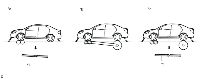
| *1 | Propeller Shaft Assembly | - | - |
| *a | 2-wheel Chassis Dynamometer | *b | 4-wheel Driven Chassis Dynamometer (Mechanical Front/back Synchronized Type) |
| *c | 4-wheel Driven Chassis Dynamometer (Electric Front/back Synchronized Type) | - | - |

|
Remove | - | - |
- NOTICE:
- ·
Do not suddenly accelerate or apply the brake.
·Failure to observe the following methods may cause AWD function effectiveness to decline, drivetrain parts to malfunction or the vehicle to move unexpectedly.
Vehicle Condition Chassis Dynamometer Vehicle Speed, Test Time Propeller Shaft Assembly 4WD ECU Assembly Connector *a
(*1)2-wheel Chassis Dynamometer No limit Remove Disconnected *b 4-wheel Driven Chassis Dynamometer (Mechanical Front/back Synchronized Type) No limit Normal Connected *c
(*1)(*2)4-wheel Driven Chassis Dynamometer (Electric Front/back Synchronized Type) No limit Remove Disconnected
- NOTICE:
- ·
(*1): Disconnect the propeller shaft assembly and 4WD ECU assembly connector and perform the test in front wheel drive. If performed under other conditions, the "AWD System Overheated 2WD Mode Engaged" message is displayed on the multi-information display and the drivetrain may be damaged.
·(*2): Do not use the electric front/back synchronized type 4-wheel driven chassis dynamometer with the propeller shaft assembly installed since the drivetrain may be damaged. (However, use with the propeller shaft assembly removed is possible)
Connect the propeller shaft assembly and 4WD ECU assembly connector and set the system to the AWD control operation permitted condition.
- NOTICE:
-
After measuring, make sure to connect the propeller shaft assembly and 4WD ECU assembly connector.
With the AWD operation status display shown on the multi-information display, drive the vehicle and check that 1 or more graduations are displayed for any wheel when accelerating.
CAUTIONS FOR TOWING DYNAMIC TORQUE VECTORING AWD VEHICLE
Tow the vehicle with all 4 wheels on the ground or lifted up. When towing the vehicle with all 4 wheels on the ground, limit the tow speed to 30 km/h or less and the tow distance to 80 km or less, and tow the vehicle in the forward direction.
- NOTICE:
-
If the vehicle is towed above this speed and beyond this distance or is towed in reverse direction, the transaxle may be affected or damaged.
Do not tow with only the front or rear wheels lifted up. If the driving system or drivetrain is malfunctioning, transport the vehicle with all 4 wheels lifted up.
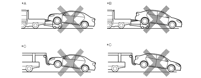
| *A | Tow Truck (Rear Wheels on the Ground) | *B | Tow Truck (Front Wheels on the Ground) |
| *C | Tow Truck (Sling-type) | - | - |
- NOTICE:
- ·
Do not use a sling-type towing method. If a sling-type tow truck is used, damage may occur to the vehicle body.
·Towing with only the front wheels or rear wheels lifted up may damage drivetrain parts or cause the wheels to jump out of the tow truck.
Use one of the methods shown below to tow the vehicle.
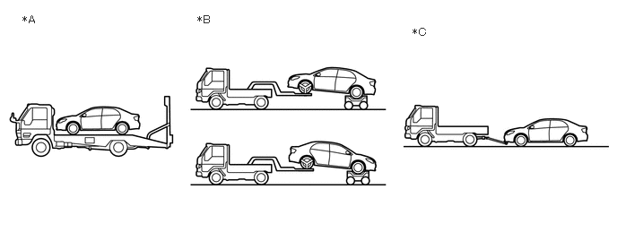
| *A | Car Carrier | *B | Tow Truck (4 Wheels Lifted) |
| *C | Tow Truck (4 Wheels on the Ground)
- Limit the tow speed to 30 km/h or less - Limit the tow distance to 80 km or less |
- | - |
- NOTICE:
- ·
If there is a malfunction in the chassis or drivetrain, use the car carrier.
·When towing the vehicle, do not use any towing method other than those shown in the illustration.
| Towing Method | Parking Brake | Transmission Shift Lever Position |
|---|---|---|
| Car Carrier | Parking brake applied* | Any position |
| Tow Truck (4 Wheels Lifted) | Parking brake applied* | Any position |
| Tow Truck (4 Wheels on the Ground) | Parking brake not applied | Shift position in N |
- CAUTION:
-
*: The braking force of the electric parking brake changes according to the tilt of the vehicle. When towing the vehicle, pull the parking brake switch 2 times (2 lock operations) to apply the maximum amount of braking force to prevent the wheels from moving unexpectedly.
- HINT:
-
The steering lock cannot be released with the battery fully depleted or the cable disconnected from the negative (-) battery terminal.