K121 CVT SHIFT LEVER INSTALLATION
PROCEDURE

 1.INSTALL TRANSMISSION FLOOR SHIFT ASSEMBLY
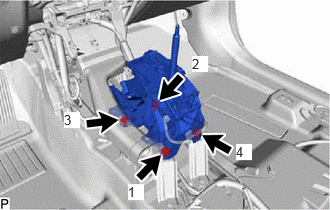
Temporarily install the transmission floor shift assembly to the vehicle body with the 4 bolts.
Tighten the 4 bolts in the order shown in the illustration.
- Torque:
- 12 N*m (122 kgf*cm, 9 ft.*lbf)
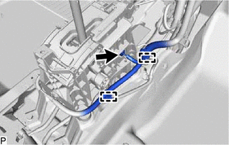
Connect the shift lock control ECU connector.
Engage the 2 clamps to connect the wire harness to the transmission floor shift assembly.
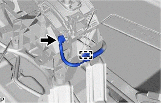
Connect the transmission control switch connector.
Engage the clamp to connect the wire harness to the transmission floor shift assembly.
33820B
2.CONNECT TRANSMISSION CONTROL CABLE ASSEMBLY
- NOTICE:
-
Before connecting the transmission control cable assembly, check that the shift lever is in N.
for SFTM Made:
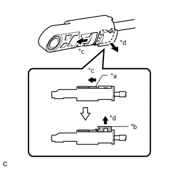
| *a | Slider |
| *b | Lock Piece |
| *c | Slide |
| *d | Pull |
Slide the slider of the transmission control cable assembly in the direction indicated by the arrow in the illustration and pull the lock piece outward.
for GTMC Made:
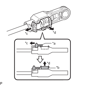
| *a | Cover |
| *b | Lock Piece |
| *c | Slide |
| *d | Pull |
Slide the cover of the transmission control cable assembly in the direction indicated by the arrow in the illustration and pull the lock piece outward.
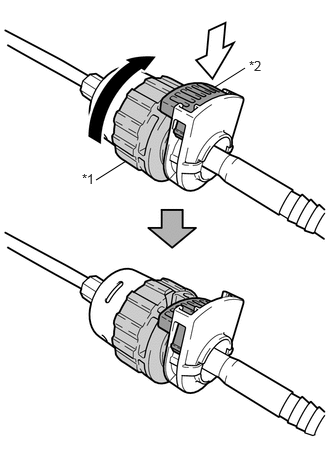
| *1 | Nut |
| *2 | Lock |

|
Rotate approximately 180° |

|
Push In |
Rotate the nut of the transmission control cable assembly approximately 180° in the direction shown in the illustration, and while holding the nut in that position, push in the lock.
- NOTICE:
-
Rotating the nut too much will damage the internal spring, and the transmission control cable assembly will not be reusable. Do not turn the nut too far.
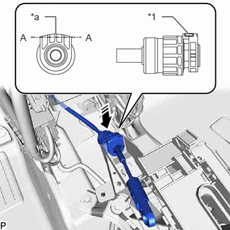
| *1 | Lock |
| *a | Protrusion |

|
Install in this Direction |
Install the transmission control cable assembly to the transmission floor shift assembly.
- NOTICE:
- ·
Install the transmission control cable assembly with the protrusion facing upwards.
·After installation, make sure that the lock is projecting from A as shown in the illustration.
·Make sure that the transmission control cable assembly is securely locked.
for SFTM Made:
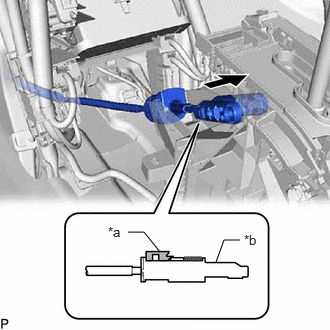
| *a | Lock Piece |
| *b | Adjuster Case |
Connect the transmission control cable assembly to the transmission floor shift assembly.
- NOTICE:
- ·
Check that the lock piece is pulled out.
·Push the end of the transmission control cable assembly all the way to the base of the transmission floor shift assembly pin.
·Connect the transmission control cable assembly so that the lock piece faces the driver side.
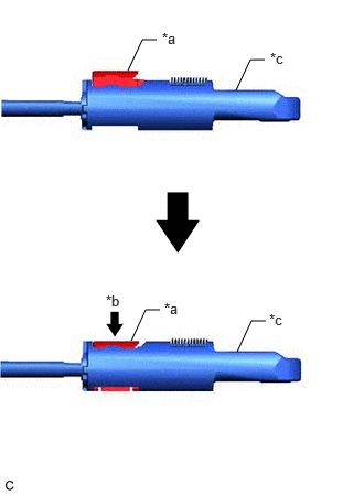
| *a | Lock Piece |
| *b | Push In |
| *c | Adjuster Case |
Push the lock piece into the adjuster case.
- NOTICE:
- ·
Check that the shift lever is in N.
·Securely push in the lock piece until the slider lock is engaged.
·Make sure that lever shaft position is not moved in shift direction during adjuster locking operation.
-Do not touch lever shaft and knob during locking operation.
-Do not pull or push adjuster case in shift direction during locking operation.
for GTMC Made:
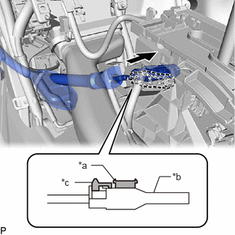
| *a | Lock Piece |
| *b | Adjuster Case |
| *c | Cover |
Connect the transmission control cable assembly to the transmission floor shift assembly.
- NOTICE:
- ·
Check that the lock piece is pulled out.
·Push the end of the transmission control cable assembly all the way to the base of the transmission floor shift assembly pin.
·Connect the transmission control cable assembly so that the lock piece faces the driver side.
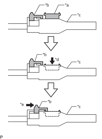
| *a | Lock Piece |
| *b | Cover |
| *c | Adjuster Case |
| *d | Push In |
| *e | Slide |
Push the lock piece into the adjuster case.
- NOTICE:
- ·
Check that the shift lever is in N.
·Make sure that lever shaft position is not moved in shift direction during adjuster locking operation.
-Do not touch lever shaft and knob during locking operation.
-Do not pull or push adjuster case in shift direction during locking operation.
Slide the cover in the direction shown by arrow until it covers projection of lock piece.
After adjusting the shift lever position, check the position and operation of the shift lever. If there is a problem, adjust the shift lever position again.
58861B
3.INSTALL NO. 1 CONSOLE BOX DUCT
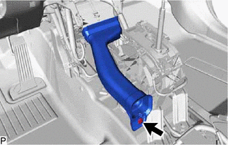
Install the No. 1 console box duct with the clip.
58810J
4.INSTALL CONSOLE BOX ASSEMBLY
5.INSPECT SHIFT LEVER POSITION
6.ADJUST SHIFT LEVER POSITION