K121 CVT TRANSMISSION CONTROL CABLE ADJUSTMENT
PROCEDURE

 1.SECURE VEHICLE
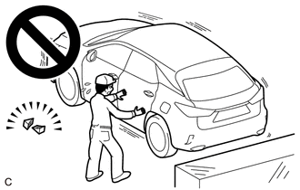
Fully apply the parking brake and chock a wheel.
- CAUTION:
-
- ·
Make sure to apply the parking brake and chock a wheel before performing this procedure.
·If the vehicle is not secure and the shift lever is moved to N, the vehicle may suddenly move, possibly resulting in an accident or serious injury.
58810J
2.REMOVE CONSOLE BOX ASSEMBLY
58861B
3.REMOVE NO. 1 CONSOLE BOX DUCT
4.ADJUST SHIFT LEVER POSITION
- NOTICE:
-
Before adjusting the transmission control cable assembly, check that the shift lever positon sensor and shift lever are in N.
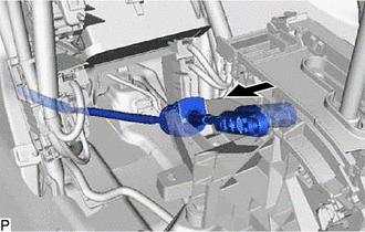
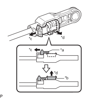
Disconnect the transmission control cable assembly from the transmission floor shift assembly.
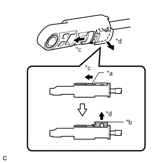
| *a | Slider |
| *b | Lock Piece |
| *c | Slide |
| *d | Pull |
for SFTM Made:
Slide the slider of the transmission control cable assembly in the direction indicated by the arrow in the illustration and pull the lock piece outward.
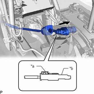
| *a | Lock Piece |
| *b | Adjuster Case |
Connect the transmission control cable assembly to the transmission floor shift assembly.
- NOTICE:
- ·
Check that the lock piece is pulled out.
·Push the end of the transmission control cable assembly all the way to the base of the transmission floor shift assembly pin.
·Connect the transmission control cable assembly so that the lock piece faces the driver side.
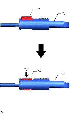
| *a | Lock Piece |
| *b | Push In |
| *c | Adjuster Case |
Push the lock piece into the adjuster case.
- NOTICE:
- ·
Check that the shift lever position sensor and shift lever are in N.
·Securely push in the lock piece until the slider lock is engaged.
·Make sure that lever shaft position is not moved in shift direction during adjuster locking operation.
-Do not touch lever shaft and knob during locking operation.
-Do not pull or push adjuster case in shift direction during locking operation.
| *a | Cover |
| *b | Lock Piece |
| *c | Slide |
| *d | Pull |
for GTMC Made:
Slide the cover of the transmission control cable assembly in the direction indicated by the arrow in the illustration and pull the lock piece outward.
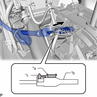
| *a | Lock Piece |
| *b | Adjuster Case |
| *c | Cover |
Connect the transmission control cable assembly to the transmission floor shift assembly.
- NOTICE:
- ·
Check that the lock piece is pulled out.
·Push the end of the transmission control cable assembly all the way to the base of the transmission floor shift assembly pin.
·Connect the transmission control cable assembly so that the lock piece faces the driver side.
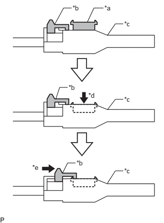
| *a | Lock Piece |
| *b | Cover |
| *c | Adjuster Case |
| *d | Push In |
| *e | Slide |
Push the lock piece into the adjuster case.
- NOTICE:
- ·
Check that the shift lever position sensor and shift lever are in N.
·Make sure that lever shaft position is not moved in shift direction during adjuster locking operation.
-Do not touch lever shaft and knob during locking operation.
-Do not pull or push adjuster case in shift direction during locking operation.
Slide the cover in the direction shown by arrow until it covers projection of lock piece.
After adjusting the shift lever position, check the position and operation of the shift lever. If there is a problem, adjust the shift lever position again.
58861B
5.INSTALL NO. 1 CONSOLE BOX DUCT
58810J
6.INSTALL CONSOLE BOX ASSEMBLY