INTERIOR PANELS / TRIM FRONT CONSOLE BOX INSTALLATION
CAUTION / NOTICE / HINT
- HINT:
-
A bolt without a torque specification is shown in the standard bolt chart.
PROCEDURE

 58810J
1.INSTALL CONSOLE BOX ASSEMBLY
58810J
1.INSTALL CONSOLE BOX ASSEMBLY
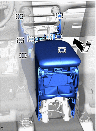

|
Install in this Direction |
Insert the guide and set the console box assembly into place in the direction indicated by the arrow shown in the illustration.
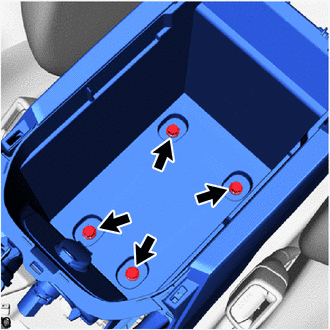
Install the 4 bolts.
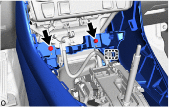
Attach the clamp to install the 2 bolts.
Connect each connector.
58815F
2.INSTALL CONSOLE BOX CARPET
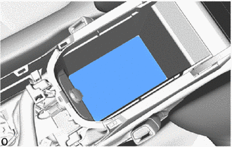
Install the console box carpet.
58825A
3.INSTALL CONSOLE BOX POCKET (w/ Console Box Tray)
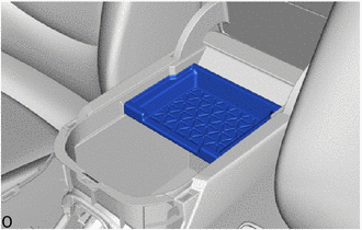
Install the console box pocket.
58816C
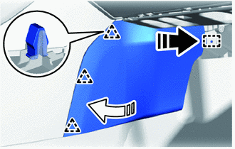
4.INSTALL FRONT NO. 1 CONSOLE BOX INSERT
|
|
Install in this Direction (1) |

|
Install in this Direction (2) |
Insert in the direction indicated by the arrow (1) shown in the illustration to attach the guide.
Rotate in the direction indicated by the arrow (2) shown in the illustration to attach the clip and install the front No. 1 console box insert.
58817A
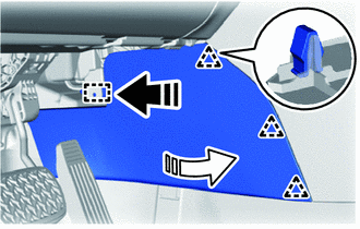
5.INSTALL FRONT NO. 2 CONSOLE BOX INSERT
|
|
Install in this Direction (1) |
|
|
Install in this Direction (2) |
Insert in the direction indicated by the arrow (1) shown in the illustration to attach the guide.
Rotate in the direction indicated by the arrow (2) shown in the illustration to attach the clip and install the front No. 2 console box insert.
58903A
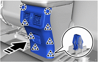
6.INSTALL REAR CONSOLE END PANEL SUB-ASSEMBLY
Connect each connector.
|
|
Install in this Direction |
Attach the clip and claw to install the rear console end panel sub-assembly in the direction indicated by the arrow shown in the illustration.
58803C
7.INSTALL CONSOLE CUP HOLDER BOX SUB-ASSEMBLY
w/ Illumination:

Connect the connector.
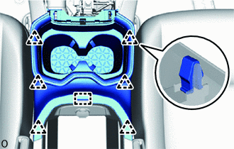
Attach the guide and clip to install the console cup holder box sub-assembly.
58805C
8.INSTALL REAR UPPER CONSOLE PANEL SUB-ASSEMBLY
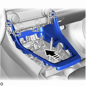
|
|
Install in this Direction |
Attach the guide in the direction indicated by the arrow shown in the illustration.
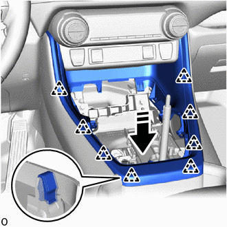
|
|
Install in this Direction |
Attach the clip to install the rear upper console panel sub-assembly in the direction indicated by the arrow shown in the illustration.
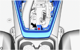
Install the bolt.
58813
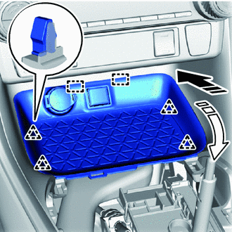
9.INSTALL UPPER CONSOLE BOX (w/o Wireless Charger)
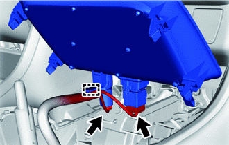
Attach the clamp and connect the 2 connectors.
|
|
Install in this Direction (1) |
|
|
Install in this Direction (2) |
Insert in the direction indicated by the arrow (1) shown in the illustration to attach the guide.
Rotate in the direction indicated by the arrow (2) shown in the illustration to attach the clip and install the upper console box.
861C0
10.INSTALL MOBILE WIRELESS CHARGER CRADLE ASSEMBLY (w/ Wireless Charger)
58804A
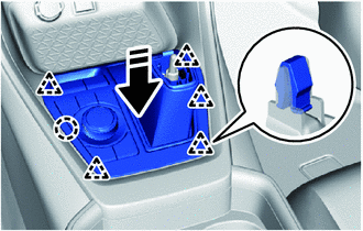
11.INSTALL UPPER CONSOLE PANEL SUB-ASSEMBLY
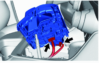
Connect the 2 connectors.
|
|
Install in this Direction |
Attach the claw and clip to install the upper console panel sub-assembly.
33504F
12.INSTALL SHIFT LEVER KNOB SUB-ASSEMBLY