M20C-FKS ENGINE CONTROL SFI SYSTEM Starter Signal Circuit
DESCRIPTION
While the engine is being cranked, current flows from terminal ST1 of the ignition switch assembly*1 or terminal STAR of the certification ECU (smart key ECU assembly)*2 to terminal STA of the ECM (STA signal).
*1: w/o Smart Entry and Start System
*2: w/ Smart Entry and Start System
WIRING DIAGRAM
Refer to DTC P061512.
CAUTION / NOTICE / HINT
- NOTICE:
- ·
Inspect the fuses for circuits related to this system before performing the following procedure.
·After the ignition switch is turned off, there may be a waiting time before disconnecting the negative (-) battery terminal.
·When disconnecting and reconnecting the battery.
Click here
- HINT:
-
When disconnecting and reconnecting the battery, there is an automatic learning function that completes learning when the respective system is used.
PROCEDURE
Check if the engine can be cranked.
- Result:
Result Proceed to Engine cannot be cranked A Engine can be cranked B
A
B
Connect the GTS to the DLC3.
Turn the ignition switch to ON.
Turn the GTS on.
Enter the following menus: Powertrain / Engine / Data List / Starter SW.
- Powertrain > Engine > Data List
-
Tester Display Starter SW - 50003 372 11
Check the value displayed on the GTS when the ignition switch is turned to the ON and engine is cranked.
- OK:
Condition GTS Display (Starter SW) Ignition switch ON OFF Engine started ON
- Result:
Proceed to OK NG
OK
NG
Inspect the ST NO. 1 relay.
- Result:
Proceed to OK NG
OK
NG
Inspect the starter assembly.
- Result:
Proceed to OK NG
OK
NG
Remove the ST NO. 1 relay from No. 1 engine room relay block and junction block assembly.
Disconnect the starter assembly connector.
Measure the resistance according to the value(s) in the table below.
- Standard Resistance:
Tester Connection Condition Specified Condition 3 (ST NO. 1 relay) - C75-1 (ST) Always Below 1 Ω 3 (ST NO. 1 relay) - C76-1 (ZYV) Always Below 1 Ω 3 (ST NO. 1 relay) or C75-1 (ST) - Body ground and other terminals Always 10 kΩ or higher 3 (ST NO. 1 relay) or C76-1 (ZYV) - Body ground and other terminals Always Below 1 Ω
- Result:
Proceed to OK NG
OK
NG
Remove the ST NO. 1 relay from the No. 1 engine room relay block and junction block assembly.
Disconnect the ECM connector.
Measure the resistance according to the value(s) in the table below.
- Standard Resistance:
Tester Connection Condition Specified Condition 2 (ST NO. 2 relay) - A125-18 (STA) Always Below 1 Ω
- Result:
Proceed to OK NG
OK
NG
Remove the ST NO. 1 relay from the No. 1 engine room relay block and junction block assembly.
Measure the resistance according to the value(s) in the table below.
- Standard Resistance:
Tester Connection Condition Specified Condition 1 (ST NO. 1 relay) - Body ground Always Below 1 Ω
- Result:
Proceed to OK NG
OK
NG
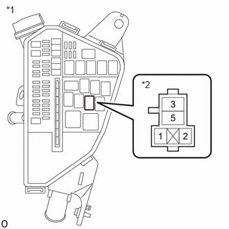
| *1 | No. 1 Engine Room Relay Block and Junction Block Assembly |
| *2 | ST NO. 1 Relay |
Remove the ST NO. 1 relay from the No. 1 engine room relay block and junction block assembly.
Measure the voltage according to the value(s) in the table below.
- Standard Voltage:
Tester Connection Condition Specified Condition 5 (ST NO. 1 relay) - Body ground Always 11 to 14 V
- Result:
Proceed to OK NG
OK
NG
Check the stop and start system.
- Result:
Result Proceed to OK (w/ Smart Entry and Start System) A OK (w/o Smart Entry and Start System) B NG C
A
B
C
Disconnect the certification ECU (smart key ECU assembly) connector.
Disconnect the ECM connector.
Disconnect the engine stop and start ECU connector.
Remove the ST NO. 1 relay from the No. 1 engine room relay block and junction block assembly.
Measure the resistance according to the value(s) in the table below.
- Standard Resistance:
Tester Connection Condition Specified Condition A126-10 (STAR) - A125-18 (STA) Always Below 1 Ω A126-10 (STAR) - A34-21 (STA) Always Below 1 Ω A126-10 (STAR), A125-18 (STA), 2 (ST NO. 1 relay) or A34-21 (STA) - Body ground Always 10 kΩ or higher
- Result:
Proceed to OK NG
OK
NG
Disconnect the ECM connector.
Disconnect the engine stop and start ECU connector.
Remove the ST NO. 2 relay from the No. 1 engine room relay block and junction block assembly.
Measure the resistance according to the value(s) in the table below.
- Standard Resistance:
Tester Connection Condition Specified Condition 3 (ST NO. 2 relay) - A125-18 (STA) Always Below 1 Ω 3 (ST NO. 2 relay) - A34-21 (STA) Always Below 1 Ω 3 (ST NO. 2 relay), A125-18 (STA) or A34-21 (STA) - Body ground Always 10 kΩ or higher
- Result:
Proceed to OK NG
OK
NG
Inspect the ST NO. 2 relay.
- Result:
Proceed to OK NG
OK
NG
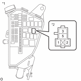
| *1 | No. 1 Engine Room Relay Block and Junction Block Assembly |
| *2 | ST NO. 2 Relay |
Remove the ST NO. 2 relay from the No. 1 engine room relay block and junction block assembly.
Measure the voltage according to the value(s) in the table below.
- Standard Voltage:
Tester Connection Condition Specified Condition 5 (ST NO. 2 relay) - Body ground Engine started 11 to 14 V
- Result:
Proceed to OK NG
OK
NG
Disconnect the ECM connector.
Remove the ST NO. 2 relay from the No. 1 engine room relay block and junction block assembly.
Measure the resistance according to the value(s) in the table below.
- Standard Resistance:
Tester Connection Condition Specified Condition C71-32 (NSR+) - 2 (ST NO. 2 relay) Always Below 1 Ω C71-33 (NSR-) - 1 (ST NO. 2 relay) Always Below 1 Ω C71-32 (NSR+) or 2 (ST NO. 2 relay) - Body ground and other terminals Always 10 kΩ or higher C71-33 (NSR-) or 1 (ST NO. 2 relay) - Body ground and other terminals Always 10 kΩ or higher
- Result:
Proceed to OK NG
OK
for 2WD: Click hereDrivetrain>K121 (CVT)>CONTINUOUSLY VARIABLE TRANSAXLE SYSTEM>P070562202405,999999,_52,_138176,_0584691,RM100000002L1NG,P070562
for AWD: Click hereDrivetrain>K121F (CVT)>CONTINUOUSLY VARIABLE TRANSAXLE SYSTEM>P070562202405,999999,_52,_138817,_0596468,RM100000002L1OH,P070562
NG
Disconnect the ignition switch assembly connector.
Remove the ST NO. 2 relay from the No. 1 engine room relay block and junction block assembly.
Measure the resistance according to the value(s) in the table below.
- Standard Resistance:
Tester Connection Condition Specified Condition G28-5 (ST1) - 5 (ST NO. 2 relay) Always Below 1 Ω G28-5 (ST1) or 5 (ST NO. 2 relay) - Body ground Always 10 kΩ or higher
- Result:
Proceed to OK NG
OK
NG
Inspect the ignition switch assembly.
- Result:
Proceed to OK NG
OK
NG
Connect the GTS to the DLC3.
Turn the ignition switch to ON.
Turn the GTS on.
Enter the following menus: Powertrain / Engine / Data List / Starter SW.
- Powertrain > Engine > Data List
-
Tester Display Starter SW - 50003 372 11
Check the value displayed on the GTS when the ignition switch is turned to the ON and the engine is cranked.
- OK:
Condition GTS Display (Starter SW) Ignition switch ON OFF Engine started ON
- Result:
Proceed to OK NG
OK
NG