M20C-FKS, M20D-FKS ENGINE MECHANICAL CYLINDER BLOCK DISASSEMBLY
CAUTION / NOTICE / HINT
The necessary procedures (adjustment, calibration, initialization or registration) that must be performed after parts are removed and installed, or replaced during cylinder head gasket removal/installation are shown below.
| Replaced Part or Performed Procedure | Necessary Procedure | Effect/Inoperative Function when Necessary Procedure not Performed | Link |
|---|---|---|---|
|
*: Even when not replacing the part, it is necessary to perform the specified necessary procedures afterinstallation. *1: Also necessary after performing a tire rotation. *2: It is not necessary to perform this procedure if the tire pressure warning valve and transmitters areinstalled to the same location. *3: When the starter assembly is replaced, "ST relay" must be also replaced. *4: The vehicle height changes because of suspension or tire replacement. *5: If transaxle compensation code read from ECM *6: If transaxle compensation code not read from ECM |
|||
| Battery terminal is disconnected/reconnected | Reset back door close position | Power Back Door System | ( 202111,999999,_59,_111831,_0505274,RM100000001ZMEG,) 202111,999999,_59,_111831,_0505274,RM100000001ZMEG,)
|
| Replacement of ECM | Update ECU security key | Vehicle Control History (RoB) are stored | (202111,999999,_V1,_111780,_0504977,RM100000001ZKRX,)
|
| Perform Vehicle Identification Number (VIN) or frame number registration | DTC is output | (202303,999999,_51,_111785,_0504416,RM1000000029BFA,)
|
|
| Code registration | Engine start | See Service Bulletin for the registration method | |
·
Transfer transaxle compensation code*5 ·
Reset transaxle compensation code*6 ·
CVT oil pressure calibration ·
Perform road test to allow ECM to learn |
·
Large shift shock ·
Deterioration of fuel efficiency |
Initialization:(202303,999999,_52,_111806,_0584611,RM1000000029R1M,)
Registration:( 202303,999999,_52,_111806,_0584611,RM1000000029R1L,)
|
|
·
Replacement of throttle body with motor assembly ·
Cleaning the deposits from the throttle body with motor assembly ·
Replacement of cam timing control motor with EDU assembly* ·
Replacement of camshaft timing gear assembly* ·
Replacement of engine assembly ·
Replacement of cylinder head subassembly ·
Replacement of camshaft (for intake or exhaust camshaft) ·
Replacement of camshaft timing exhaust gear assembly ·
Replacement of port fuel injector assembly ·
Replacement of direct fuel injector assembly ·
Replacement of fuel pump assembly (for high pressure side) ·
Replacement of ignition coil assembly ·
Replacement of Spark plug ·
Replacement of EGR valve assembly ·
Gas leak from exhaust system is repaired |
Inspection after repair | ·
Poor idle, etc. ·
Engine start function, etc. |
(202303,999999,_51,_111785,_0504416,RM1000000029BFF,)
|
| Replacement of Starter assembly*3 | Clear the number of starteroperations | Stop and Start System | (202111,999999,_51,_111803,_0509671,RM1000000020651,)
|
| Replacement of Battery | Integrated current valueinitialization | ||
·
Replacement of Continuously variabletransaxle assembly ·
Replacement of CVT Fluid |
Air bleed the oil pump withmotor assembly | ||
| Replacement of continuously variable transaxle assembly | ·
Input transaxle compensation code into ECM ·
Perform reset memory ·
CVT oil pressure calibration ·
Perform road test to allow ECM to learn |
·
Large shift shock ·
Deterioration of fuel efficiency |
(202303,999999,_52,_111806,_0584611,RM1000000029R1M,)for K121, K121F Initialization
( 202303,999999,_52,_111806,_0584611,RM1000000029R1L,)for K121, K121F Registration
|
| Replacement of CVT fluid | ATF thermal degradation estimate reset | The value of the Data List item "ATF Thermal Degradation Estimate" is not estimated correctly | (202303,999999,_52,_111806,_0584611,RM1000000029R1M,)
|
| Tires | ·
Initialization*1*2 ·
Tire Position Identification*1*2 |
Tire Pressure Warning System | Refer to Procedures Necessary When Replacing Parts (for Tire Pressure Warning System) table below |
| Suspension parts*4 | Parking assist ECU initialization | Panoramic View Monitor System | (202409,999999,_56,_111825,_0500432,RM100000002O1F6,)
|
| Rear television camera assembly optical axis (Back camera position setting) | Parking Assist Monitor System | (202409,999999,_56,_111825,_0524148,RM100000002OUWG,)
|
|
| Front wheel alignment adjustment | ·
Perform reset memory ·
Perform "Calibration" |
·
DTCs are stored ·
ABS warning light illuminates ·
Slip indicator light illuminates ·
Electronically controlled brake system does not operate correctly |
(202203,999999,_54,_111814,_0500728,RM1000000022HI0,)
|
| Front bumper assembly* | Front television camera view adjustment | Panoramic View Monitor System | (202409,999999,_56,_111825,_0500432,RM100000002O1F6,)
|
- HINT:
-
When the cable is disconnected / reconnected to the battery terminal, systems temporarily stop operating. However, each system has a function that completes learning the first time the system is used.
Items for which learning is completed by driving the vehicle Effect/Inoperative Function when Necessary Procedure not Performed Necessary Procedure Link Lane Tracing Assist System Drive the vehicle straight ahead at 15 km/h (10 mph) or more for 1 seconds or more. ( 202111,999999,_95,_111850,_0502173,RM100000001Z92I,)
Pre-collision System Stop and Start System Idle the engine for approximately 5 to 60minutes or drive the vehicle until stop andstart control is permitted ( 202406,999999,_51,_111803,_0509671,RM100000002KOGF,)
Items for which learning is completed by operating the vehicle normally Effect/Inoperative Function when Necessary Procedure not Performed Necessary Procedure Link Power Door Lock Control System
·Back door opener
Perform door unlock operation with door control switch or electrical key transmitter sub-assembly switch. ( 202111,999999,_58,_111830,_0505351,RM100000001ZMT3,)
Air Conditioning System After the ignition switch is turned to ON, the servo motor standard position is recognized. -
PROCEDURE

 12211
1.REMOVE NO. 1 VENTILATION CASE
12211
1.REMOVE NO. 1 VENTILATION CASE
- CAUTION:
-
Do not disassemble except if the No. 1 ventilation case to be damaged.
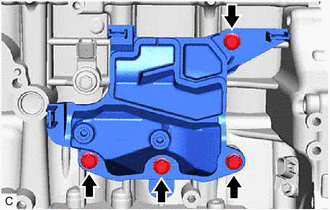
Remove the 4 bolts and No. 1 ventilation case from the cylinder block sub-assembly.
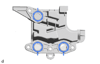
Remove the 3 oil separator gaskets from the No. 1 ventilation case.
2.INSPECT CONNECTING ROD THRUST CLEARANCE
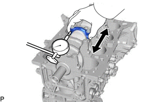
Using a dial indicator, measure the thrust clearance while moving the connecting rod sub-assembly back and forth.
- Standard Thrust Clearance:
0.160 to 0.512 mm (0.00630 to 0.0202 in.)
- Maximum Thrust Clearance:
0.512 mm (0.0202 in.)
- HINT:
-
If the thrust clearance is more than the maximum, replace the connecting rod. If necessary, replace the crankshaft.
3.INSPECT CONNECTING ROD OIL CLEARANCE
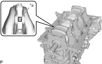
| *a | Alignment Mark |
Note the alignment marks on the connecting rod and connecting rod cap so that they can be reinstalled to their original locations.
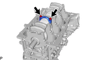
Using an E12 "TORX" socket wrench, remove the 2 connecting rod bolts and connecting rod cap.
- HINT:
-
Keep the connecting rod bearing and connecting rod cap together.
Clean the crank pin and connecting rod bearing.
Check the crank pin and connecting rod bearing for pitting and scratches.
- HINT:
-
If the crank pin or connecting rod bearing is damaged, replace the connecting rod bearings. If necessary, replace the crankshaft.
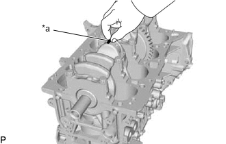
| *a | Plastigage |
Lay a strip of Plastigage on the crank pin.
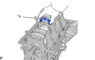
| *a | Front Mark |
Check that the front mark of the connecting rod cap is facing the correct direction, and install the connecting rod cap to the connecting rod.
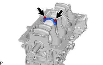
Apply a light coat of engine oil to the threads and under the heads of the 2 connecting rod bolts.
Using an E12 "TORX" socket wrench, install and alternately tighten the 2 connecting rod bolts in several steps.
- Torque:
- 38 N*m (387 kgf*cm, 28 ft.*lbf)
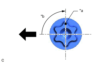
| *a | Paint Mark |
| *b | 90° |

|
Front of Engine |
Mark the front of each connecting rod bolt with paint.
Tighten the connecting rod bolts 90° as shown in the illustration.
- NOTICE:
-
Do not turn the crankshaft during the measurement.
Remove the 2 connecting rod bolts and connecting rod cap.
- HINT:
-
Keep the connecting rod bearing and connecting rod cap together.

| *a | Plastigage |
| *b | 1, 2 or 3 Mark |
Measure the Plastigage at its widest point.
- Standard Oil Clearance:
0.032 to 0.065 mm (0.00126 to 0.00256 in.)
- Maximum Oil Clearance:
0.065 mm (0.00256 in.)
- HINT:
- ·
If the oil clearance is more than the maximum, replace the connecting rod bearings. If necessary, replace the crankshaft.
·If replacing a connecting rod bearing, select a new one with the same number as marked on the connecting rod cap. There are 3 sizes of standard connecting rod bearings, marked "1", "2" or "3" accordingly.
- Standard Connecting Rod Big End Inside Diameter:
Mark Specified Condition 1 51.000 to 51.008 mm (2.00787 to 2.00818 in.) 2 51.008 to 51.016 mm (2.00818 to 2.00850 in.) 3 51.016 to 51.024 mm (2.00850 to 2.00881 in.)
- Standard Connecting Rod Bearing Center Wall Thickness:
Mark Specified Condition 1 1.483 to 1.487 mm (0.05839 to 0.05854 in.) 2 1.487 to 1.491 mm (0.05854 to 0.05870 in.) 3 1.491 to 1.495 mm (0.05870 to 0.05886 in.)
- Standard Crank Pin Diameter:
47.992 to 48.000 mm (1.88945 to 1.88976 in.)
- NOTICE:
-
Remove the Plastigage completely after the measurement.
Perform the inspection above for each cylinder.
4.REMOVE PISTON WITH CONNECTING ROD
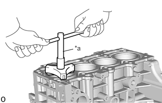
| *a | Ridge Reamer |
Using a ridge reamer, remove all the carbon from the top of each cylinder.
Remove the 8 connecting rod bolts, 4 connecting rod caps and 4 connecting rod bearings.
Push the 4 pistons, 4 connecting rods and 4 connecting rod bearings out through the top of the cylinder block sub-assembly.
- HINT:
- ·
Keep the connecting rod bearings, connecting rods and connecting rod caps together.
·Arrange the removed parts in such a way that they can be reinstalled to their original locations.
5.REMOVE CONNECTING ROD BEARING
Remove the 8 connecting rod bearings from the 4 connecting rods and 4 connecting rod caps.
- HINT:
-
Arrange the removed parts in such a way that they can be reinstalled to their original locations.
6.INSPECT CRANKSHAFT THRUST CLEARANCE
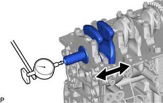
Using a dial indicator, measure the crankshaft thrust clearance while prying the crankshaft back and forth with a screwdriver.
- Standard Thrust Clearance:
0.02 to 0.22 mm (0.000787 to 0.00866 in.)
- Maximum Thrust Clearance:
0.22 mm (0.00866 in.)
- HINT:
-
If the thrust clearance is more than the maximum, replace the crankshaft thrust washers as a set. If necessary, replace the crankshaft.
- Standard Thrust Washer Thickness:
2.415 to 2.470 mm (0.0951 to 0.0972 in.)
13411
7.REMOVE CRANKSHAFT
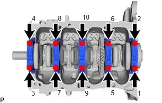
Uniformly loosen and remove the 10 crankshaft bearing cap set bolts in several steps in the order shown in the illustration.
Remove the 5 crankshaft bearing caps from the cylinder block sub-assembly.
- HINT:
- ·
Keep the No. 2 crankshaft bearings and crankshaft bearing caps together.
·Arrange the removed parts in such a way that they can be reinstalled to their original locations.
Remove the crankshaft from the cylinder block sub-assembly.
- HINT:
-
Keep the No. 1 crankshaft bearings and crankshaft thrust washers together with the cylinder block sub-assembly.
Check each crankshaft journal and crankshaft bearing for pitting and scratches.
If the journal or crankshaft bearing is damaged, replace the crankshaft bearings. If necessary, replace the crankshaft.
11791
8.REMOVE CRANKSHAFT THRUST WASHER
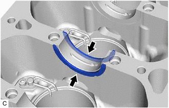
Remove the 2 crankshaft thrust washers from the No. 3 journal position of the cylinder block sub-assembly.
9.REMOVE CRANKSHAFT BEARING
Remove the 5 No. 1 crankshaft bearings and 5 No. 2 crankshaft bearings from the cylinder block sub-assembly and 5 crankshaft bearing caps.
- HINT:
-
Arrange the removed parts in such a way that they can be reinstalled to their original locations.
13011
10.REMOVE PISTON RING SET

| *a | Piston Ring Expander |
Using a piston ring expander, remove the No. 1 compression ring and No. 2 compression ring from the piston.
Remove the oil ring expander, upper side rail and lower side rail from the piston by hand.
- HINT:
-
Arrange the removed parts in such a way that they can be reinstalled to their original locations.
13101A
11.REMOVE PISTON PIN HOLE SNAP RING
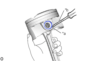
| *a | Front Mark Cutout Portion |
| *b | Protective Tape |
Using a screwdriver, pry out the 2 piston pin hole snap rings from the piston.
- HINT:
-
Tape the screwdriver tip before use.
12.REMOVE PISTON
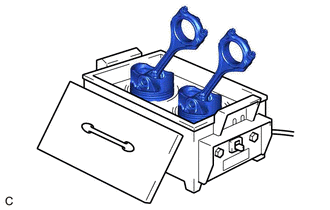
Gradually heat each piston to between 80 and 90°C (176 and 194°F).
- CAUTION:
-
Be sure to wear protective gloves.
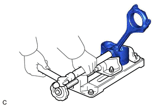
Using a brass bar and a hammer, lightly tap out the piston pin and remove the connecting rod.
- HINT:
- ·
The piston and piston pin are a matched set.
·Arrange the removed parts in such a way that they can be reinstalled to their original locations.
15708
13.REMOVE NO. 1 OIL NOZZLE SUB-ASSEMBLY
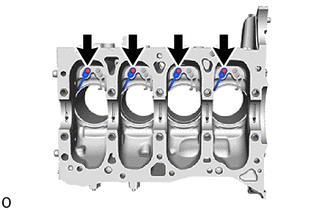
Using a 5 mm hexagon socket wrench, remove the 4 bolts and 4 No. 1 oil nozzle sub-assemblies from the cylinder block sub-assembly.
15709
14.REMOVE NO. 2 OIL NOZZLE SUB-ASSEMBLY
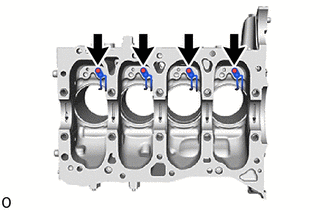
Using a 5 mm hexagon socket wrench, remove the 4 bolts and 4 No. 2 oil nozzle sub-assemblies from the cylinder block sub-assembly.