STEERING COLUMN STEERING COLUMN ASSEMBLY INSTALLATION
PROCEDURE

 1.ALIGN FRONT WHEELS FACING STRAIGHT AHEAD
45250
2.INSTALL STEERING COLUMN ASSEMBLY
- NOTICE:
-
Make sure that the wire harness is not interfering with the steering column assembly.
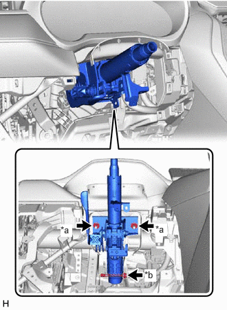
| *a | Nut |
| *b | Bolt |
Install the steering column assembly with the bolt and 2 nuts.
- Torque:
- 36 N*m (367 kgf*cm, 27 ft.*lbf)
- NOTICE:
- ·
After temporarily tightening the bolt, fully tighten the 2 nuts then fully tighten the bolt.
·After the column is installed, check the tilt and telescopic operation.
·If a large amount of force is required to operate the tilt and telescopic mechanism or abnormal noise occurs, loosen the nuts and move the bracket forward or backward until the tilt and telescopic operation works smoothly.
Tighten the nuts and check the tilt and telescopic operation again.
Connect each connector and engage each wire harness clamp to the steering column assembly.
45220
3.INSTALL STEERING INTERMEDIATE SHAFT ASSEMBLY

| *a | Matchmark |

|
Install in this direction |
Align the matchmarks on the steering intermediate shaft assembly and steering column assembly.
Install the steering intermediate shaft assembly to the steering column assembly.
Install the bolt.
- Torque:
- 35 N*m (357 kgf*cm, 26 ft.*lbf)
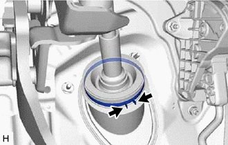
Tighten the clamp.
45253
4.INSTALL STEERING COLUMN HOLE COVER
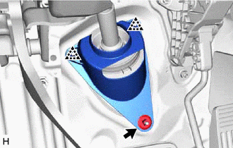
Install the steering column hole cover with the 2 clips.
Install the clip.
Return the floor carpet.
45220
5.CONNECT STEERING INTERMEDIATE SHAFT ASSEMBLY
6.INSTALL FRONT WHEEL LH
87211A
7.INSTALL NO. 2 AIR DUCT
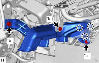
| *a | Bolt |
| *b | Screw |
Engage the 3 claws to install a new No. 2 air duct.
Install the 2 bolts.
- Torque:
- 9.8 N*m (100 kgf*cm, 87 in.*lbf)
Install the screw.
73900
8.INSTALL LOWER NO. 1 INSTRUMENT PANEL AIRBAG ASSEMBLY
9.INSTALL TURN SIGNAL SWITCH ASSEMBLY WITH SPIRAL CABLE SUB-ASSEMBLY
- NOTICE:
- ·
Do not remove/install the spiral cable with sensor sub-assembly with the auxiliary battery connected and the ignition switch ON.
·Do not rotate the spiral cable with sensor sub-assembly without the steering wheel assembly installed, with the auxiliary battery connected and the ignition switch ON.
·Ensure that the steering wheel assembly is installed and aligned straight when inspecting the steering sensor.
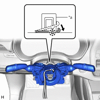
| *a | Clamp |
Using pliers, expand the clamp.
While holding the clamp expanded, install the turn signal switch assembly with spiral cable sub-assembly to the steering column assembly and engage the claw.
Return the clamp to its original position.
Connect the connectors to the turn signal switch assembly with spiral cable sub-assembly.
45286B
10.INSTALL UPPER STEERING COLUMN COVER
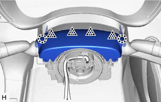
Engage the 2 claws and 4 clips to connect the upper steering column cover.
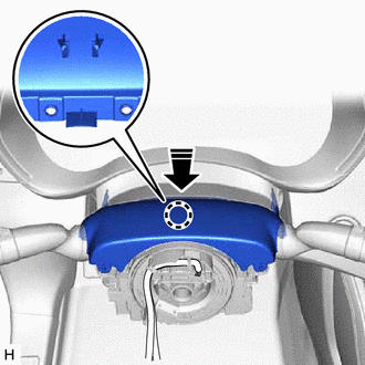
|
|
Install in this direction |
Engage the claw to install the upper steering column cover.
45287
11.INSTALL LOWER STEERING COLUMN COVER
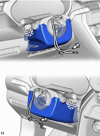
Engage the 2 claws to install the lower steering column cover.
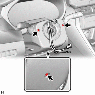
Install the 3 screws.
12.ALIGN FRONT WHEELS FACING STRAIGHT AHEAD
13.INSPECT AND ADJUST SPIRAL CABLE WITH SENSOR SUB-ASSEMBLY
14.INSTALL STEERING WHEEL ASSEMBLY
15.CHECK STEERING WHEEL CENTER POINT
45130
16.INSTALL HORN BUTTON ASSEMBLY