HEATING / AIR CONDITIONING CONDENSER REMOVAL
CAUTION / NOTICE / HINT
The necessary procedures (adjustment, calibration, initialization, or registration) that must be performed after parts are removed and installed, or replaced during cooler condenser assembly removal/installation are shown below.
| Replaced Part or Performed Procedures | Necessary Procedures | Effect/Inoperative Function When Necessary Procedures are not Performed | Link |
|---|---|---|---|
|
*: Even when not replacing the part, it is necessary to perform the specified necessary procedures after installation. |
|||
| Front bumper assembly* | Front television camera view adjustment | Panoramic View Monitor System | ( 202409,999999,_56,_111825,_0500432,RM100000002O1F6,) 202409,999999,_56,_111825,_0500432,RM100000002O1F6,)
|
| Replacement or removal and installation of 2 or more parts:
·
Front television camera assembly, radiator grille sub-assembly or front bumper assembly ·
Rear television camera assembly ·
Side television camera assembly LH or outer rear view mirror assembly LH ·
Side television camera assembly RH or outer rear view mirror assembly RH |
Television camera view adjustment | Panoramic View Monitor System | (202409,999999,_56,_111825,_0500432,RM100000002O1F6,)
|
PROCEDURE

 1. RECOVER REFRIGERANT FROM REFRIGERATION SYSTEM
2.REMOVE FRONT BUMPER ASSEMBLY
for SFTM Made:
for GTMC Made:
17750A
3.REMOVE INLET AIR CLEANER ASSEMBLY
for M20C-FKS, M20D-FKS:
for A25D-FXS, A25F-FXS:
16681A
4.REMOVE UPPER RADIATOR AIR GUIDE PLATE
for M20C-FKS, M20D-FKS:
for A25D-FXS, A25F-FXS:
52614
5.REMOVE NO. 2 FRONT BUMPER ENERGY ABSORBER
52021
6.REMOVE FRONT BUMPER REINFORCEMENT SUB-ASSEMBLY
16562M
7.REMOVE NO. 2 RADIATOR TO SUPPORT SEAL
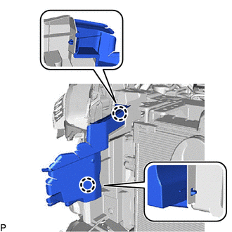
Disengage the 2 claws to remove the No. 2 radiator to support seal.
16563D
8.REMOVE NO. 3 RADIATOR TO SUPPORT SEAL
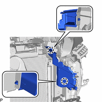
Disengage the 2 claws to remove the No. 3 radiator to support seal.
16691A
9.REMOVE FRONT RADIATOR SIDE AIR GUIDE PLATE RH
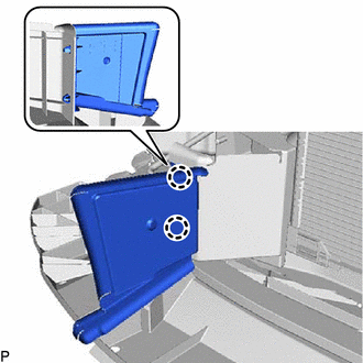
Disengage the 2 claws to remove the front radiator side air guide plate RH.
16695A
10.REMOVE FRONT RADIATOR SIDE AIR GUIDE PLATE LH
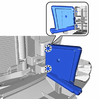
Disengage the 2 claws to remove the front radiator side air guide plate LH.
16593B
11.REMOVE NO. 1 RADIATOR AIR GUIDE RH
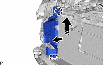

|
Remove in this Direction |
Remove the clip.
Disengage the claw and guide as shown in the illustration to remove the No. 1 radiator air guide RH.
16595B
12.REMOVE NO. 1 RADIATOR AIR GUIDE LH
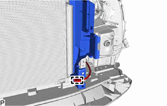
Disengage the clamp.
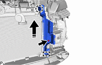
|
|
Remove in this Direction |
Remove the clip.
Disengage the claw and guide as shown in the illustration to remove the No. 1 radiator air guide LH.
53510
13.REMOVE HOOD LOCK ASSEMBLY
53630
14.DISCONNECT HOOD LOCK CONTROL CABLE ASSEMBLY
for M20C-FKS, M20D-FKS:
for A25D-FXS, A25F-FXS:
53205
15.REMOVE UPPER RADIATOR SUPPORT SUB-ASSEMBLY
for M20C-FKS, M20D-FKS:
for A25D-FXS, A25F-FXS:
88711
16.DISCONNECT NO. 1 COOLER REFRIGERANT DISCHARGE HOSE
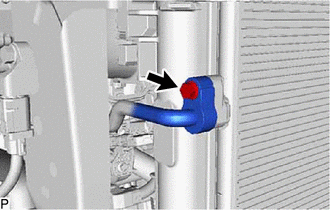
Remove the bolt.
Disconnect the No. 1 cooler refrigerant discharge hose.
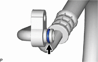
Remove the O-ring from the No. 1 cooler refrigerant discharge hose.
- NOTICE:
-
Seal the openings of the disconnected parts using vinyl tape to prevent entry of moisture and foreign matter.
88710E
17.DISCONNECT AIR CONDITIONING TUBE AND ACCESSORY ASSEMBLY
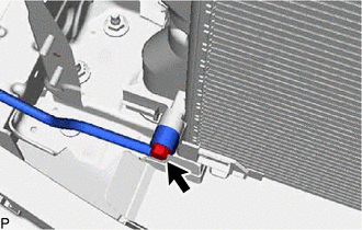
Remove the bolt.
Disconnect the air conditioning tube and accessory assembly.
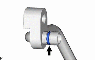
Remove the O-ring from the air conditioning tube and accessory assembly.
- NOTICE:
-
Seal the openings of the disconnected parts using vinyl tape to prevent entry of moisture and foreign matter.
884A0
18.REMOVE COOLER CONDENSER ASSEMBLY
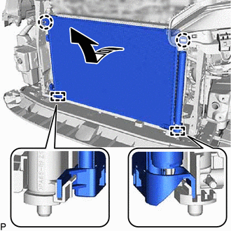
|
|
Remove in this Direction |
Disengage the 2 claws and 2 guides, and remove the cooler condenser assembly as shown in the illustration.
- NOTICE:
-
Do not damage the cooler condenser assembly and radiator assembly when removing the cooler condenser assembly.