EXTERIOR PANELS / TRIM FRONT BUMPER(for SFTM Made) REMOVAL
CAUTION / NOTICE / HINT
The necessary procedures (adjustment, calibration, initialization, or registration) that must be performed after parts are removed and installed, or replaced during front bumper assembly removal/installation are shown below.
| Replaced Part or Performed Procedures | Necessary Procedures | Effect/Inoperative Function When Necessary Procedures are not Performed | Link |
|---|---|---|---|
|
*: Even when not replacing the part, it is necessary to perform the specified necessary procedures after installation. |
|||
·
Front bumper assembly* ·
Front television camera assembly* ·
Radiator grille sub-assembly* |
Front television camera view adjustment | Panoramic View Monitor System | ( 202111,202406,_56,_111825,_0500432,RM100000001Z2GE,202406,202409,_56,_111825,_0694751,RM100000002LTJL,202409,999999,_56,_111825,_0500432,RM100000002O1F6,) 202111,202406,_56,_111825,_0500432,RM100000001Z2GE,202406,202409,_56,_111825,_0694751,RM100000002LTJL,202409,999999,_56,_111825,_0500432,RM100000002O1F6,)
|
| Replacement or removal and installation of 2 or more parts:
·
Front television camera assembly, radiator grille sub-assembly or front bumper assembly ·
Rear television camera assembly ·
Side television camera assembly LH or outer rear view mirror assembly LH ·
Side television camera assembly RH or outer rear view mirror assembly RH |
Television camera view adjustment | Panoramic View Monitor System | (202111,202406,_56,_111825,_0500432,RM100000001Z2GE,202406,202409,_56,_111825,_0694751,RM100000002LTJL,202409,999999,_56,_111825,_0500432,RM100000002O1F6,)
|
- HINT:
-
When the front bumper is damaged or deformed due to an accident or contact with other objects, etc., or the bumper installation area on the body is repaired, it is necessary to perform millimeter wave radar sensor adjustment.
-
Target Adjustment (Triangle Target):
-
Target Adjustment (Flat Surface Target):
-
Driving Adjustment:
PROCEDURE

 1.REMOVE FRONT BUMPER ASSEMBLY
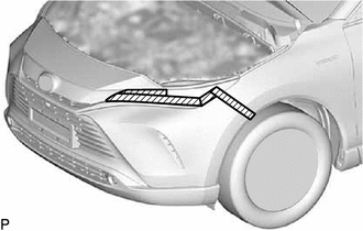

|
Protective Tape |
Apply protective tape around the front bumper assembly.
- HINT:
-
Use the same procedure for the RH side and LH side.
As shown in the illustration, pull the front bumper assembly horizontally to release each claw and disengage the front fender liner retainer.
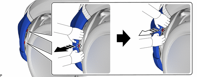

|
Remove in this Direction (1) | 
|
Remove in this Direction (2) |
- HINT:
-
Use the same procedure for the RH side and LH side.
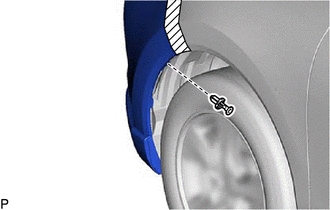
Remove the clip.
- HINT:
-
Use the same procedure for the RH side and LH side.
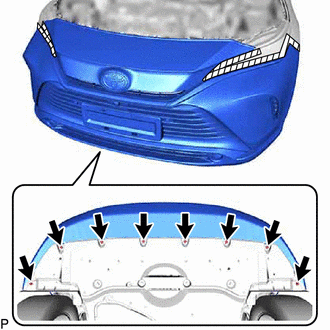
Remove the 8 screws.
|
|
Remove in this Direction |
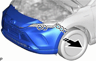
Disengage the 5 claws as shown in the illustration.
- HINT:
-
Use the same procedure for the LH side and RH side.
|
|
Remove in this Direction |
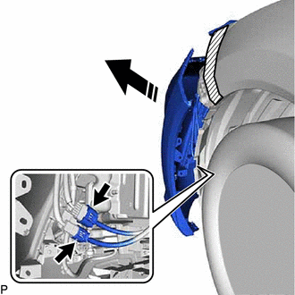
Pull back the side of the front bumper assembly and disconnect the 2 connectors.
- NOTICE:
-
Do not apply excessive force when pulling back the front bumper assembly.
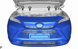
Remove the 4 bolts.
|
|
Remove in this Direction |
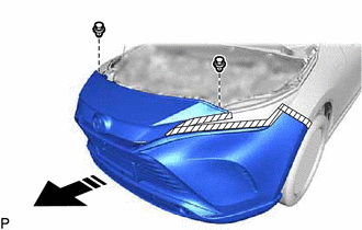
Remove the 2 clips and front bumper assembly as shown in the illustration.