NAVIGATION / MULTI INFO DISPLAY NAVIGATION SYSTEM B15A387 Stereo Component Amplifier Missing Message
DESCRIPTION
This DTC is stored when the navigation receiver assembly detects that the stereo component amplifier assembly has disconnected.
| DTC No. | Detection Item | DTC Detection Condition | Trouble Area | DTC Output from | Priority |
|---|---|---|---|---|---|
| B15A387 | Stereo Component Amplifier Missing Message | When 60 seconds has elapsed after turning the ignition switch to ON and the stereo component amplifier assembly cannot be detected, the stereo component amplifier assembly is judged to be disconnected after comparison with the past registered devices history.
(2 trip detection logic) |
·
Navigation receiver assembly ·
Stereo component amplifier assembly ·
Harness or connector |
Navigation System | A |
WIRING DIAGRAM
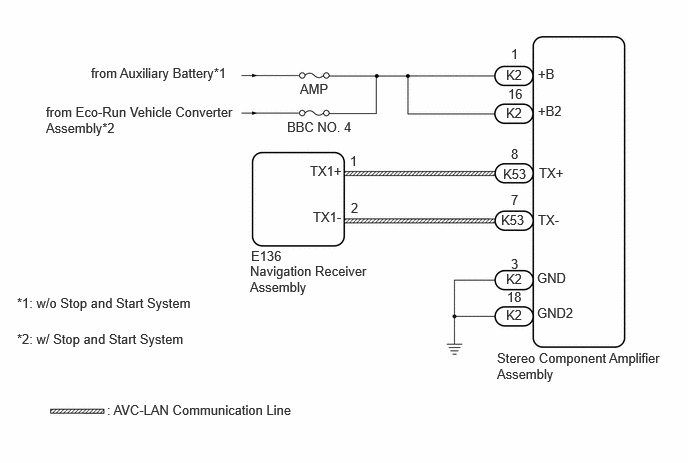
CAUTION / NOTICE / HINT
- NOTICE:
- ·
Inspect the fuses for circuits related to this system before performing the following procedure.
·Depending on the parts that are replaced during vehicle inspection or maintenance, performing initialization, registration or calibration may be needed.
- HINT:
-
There may be a communication malfunction due to noise affecting communication between devices on the AVC-LAN.
PROCEDURE
Pre-procedure1
Disconnect the K2 stereo component amplifier assembly connector.
Procedure1
Measure the resistance according to the value(s) in the table below.
- Standard Resistance:
Tester Connection Condition Specified Condition Click Location & Routing(K2)Location & Routingewd_type=routing;type=c;code=K2
Click Connector(K2)Body>Floor Wire>Stereo Component Amplifier Assemblyewd_type=component;type=c;code=K2;pinno=3,18
K2-3 (GND) - Body ground Always Below 1 Ω K2-18 (GND2) - Body ground Always Below 1 Ω
Measure the voltage according to the value(s) in the table below.
- Standard Voltage:
Tester Connection Condition Specified Condition Click Location & Routing(K2)Location & Routingewd_type=routing;type=c;code=K2
Click Connector(K2)Body>Floor Wire>Stereo Component Amplifier Assemblyewd_type=component;type=c;code=K2;pinno=1,16
K2-1 (+B) - Body ground IG OFF 11 to 14 V*1
9.5 to 16 V*2K2-16 (+B2) - Body ground IG OFF 11 to 14 V*1
9.5 to 16 V*2
*1: w/o Stop and Start System
*2: w/ Stop and Start System
- Result:
Proceed to OK NG
Post-procedure1
None
OK
NG
Pre-procedure1
Disconnect the E136 navigation receiver assembly connector.
Disconnect the K53 stereo component amplifier assembly connector.
Procedure1
Measure the resistance according to the value(s) in the table below.
- Standard Resistance:
Tester Connection Condition Specified Condition Click Location & Routing(E136,K53)Location & Routingewd_type=routing;type=c,c;code=E136,K53
Click Connector(E136)Instrument Panel>Instrument Panel Wire / Telephone Computer Wire>Navigation Receiver Assemblyewd_type=component;type=c;code=E136;pinno=1,2
Click Connector(K53)Body>Floor Wire>Stereo Component Amplifier Assemblyewd_type=component;type=c;code=K53;pinno=8,7
E136-1 (TX1+) - K53-8 (TX+) Always Below 1 Ω E136-2 (TX1-) - K53-7 (TX-) Always Below 1 Ω E136-1 (TX1+) or K53-8 (TX+) - Body ground Always 10 kΩ or higher E136-2 (TX1-) or K53-7 (TX-) - Body ground Always 10 kΩ or higher
- Result:
Proceed to OK NG
Post-procedure1
None
OK
NG
Replace the stereo component amplifier assembly with a new or known good one.
- HINT:
- Result:
Proceed to NEXT
NEXT
Clear the DTCs.
- Body Electrical > Navigation System > Clear DTCs
- 50002 496
- Result:
Proceed to NEXT
NEXT
Pre-procedure1
Turn the ignition switch off.
Turn the ignition switch to ON and wait for 60 seconds.
Turn the ignition switch off.
Turn the ignition switch to ON and wait for 60 seconds.
Procedure1
Check for DTCs and proceed to the following step.
- Body Electrical > Navigation System > Trouble Codes
- 50001 496
- Result:
Result Proceed to DTCs are not output A B15A387 is output B
Post-procedure1
None
A
B