PARK ASSIST / MONITORING PANORAMIC VIEW MONITOR SYSTEM "CHK" message(s) are displayed on the SIGNAL CHECK screen.
DESCRIPTION
On the Signal Check screen, it is possible to check if the signals sent to the parking assist ECU are normal.
- HINT:
- ·
On the Signal Check screen, "OK" (blue) is displayed for items with a normal inspection result or input state.
·On the Signal Check screen, "CHK" (red) is displayed for items with an abnormal inspection result or input state.
·Displayed items may differ depending on vehicle specifications.
| Item | Signal Input Method | Detail | DTC Output when Abnormal Result is Displayed | Signal Receiver |
|---|---|---|---|---|
| CAN | CAN communication | CAN communication signal | DTC is output | Related ECUs |
| CAMERA SW | Vehicle wire harness | Panoramic view monitor switch signal input state | DTC is not output | Panoramic view monitor switch |
| SHIFT | Vehicle wire harness | Shift position switch signal | DTC is not output | BKUP LP relay |
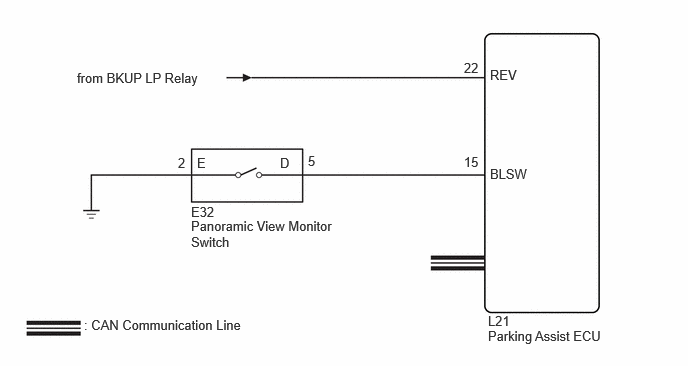
WIRING DIAGRAM
CAUTION / NOTICE / HINT
- NOTICE:
-
Depending on the parts that are replaced or operations that are performed during vehicle inspection or maintenance, calibration of other systems as well as the panoramic view monitor system may be needed.
PROCEDURE
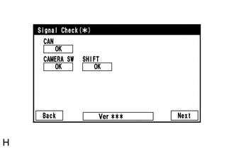
Check which items display on the signal check screen.
- Result:
Result Proceed to "CAMERA SW" displays "CHK" (red) A "SHIFT" displays "CHK" (red) B "CAN" displays "CHK" (red) C
A
B
C
for HV Model:
for Gasoline Model:
Disconnect the E32 panoramic view monitor switch (combination switch assembly) connector.
Disconnect the L21 parking assist ECU connector.
Measure the resistance according to the value(s) in the table below.
- Standard Resistance:
Tester Connection Condition Specified Condition Click Location & Routing(E32,L21)Location & Routingewd_type=routing;type=c,c;code=E32,L21
Click Connector(E32)Instrument Panel>Instrument Panel Wire / Telephone Computer Wire>Panoramic View Monitor Switchewd_type=component;type=c;code=E32;pinno=5,2
Click Connector(L21)Instrument Panel>No. 2 Floor Wire>Parking Assist ECUewd_type=component;type=c;code=L21;pinno=15
E32-5 (D) - L21-15 (BLSW) Always Below 1 Ω E32-2 (E) - Body ground Always Below 1 Ω E32-5 (D) or L21-15 (BLSW) - Body ground Always 10 kΩ or higher
- Result:
Proceed to OK NG
OK
NG
- Result:
Proceed to OK NG
OK
NG
Check that the back-up light comes on.
- OK:
The back-up light comes on.
- Result:
Proceed to OK NG
OK
NG
Disconnect the parking assist ECU connector.
Measure the voltage according to the value(s) in the table below.
- Standard Voltage:
Tester Connection Condition Specified Condition Click Location & Routing(L21)Location & Routingewd_type=routing;type=c;code=L21
Click Connector(L21)Instrument Panel>No. 2 Floor Wire>Parking Assist ECUewd_type=component;type=c;code=L21;pinno=22
L21-22 (REV) - Body ground Ignition switch ON, shift lever in R 11 to 14 V L21-22 (REV) - Body ground Ignition switch ON, shift lever not in R Below 1 V
- Result:
Proceed to OK NG
OK
NG