METER / GAUGE / DISPLAY METER / GAUGE SYSTEM(for TFT Meter Type) B132187 Lost Communication with EMV Missing Message
DESCRIPTION
After the combination meter assembly has started, the combination meter assembly attempts to detect the navigation receiver assembly by performing communication via local bus.
This DTC is stored when the navigation receiver assembly has been detected but communication between the combination meter assembly and navigation receiver assembly is interrupted.
| DTC No. | Detection Item | DTC Detection Condition | Trouble Area | DTC Output from | Priority |
|---|---|---|---|---|---|
| B132187 | Lost Communication with EMV Missing Message | Diagnosis Condition:
·
The combination meter assembly has started ·
The navigation receiver assembly has started Malfunction Status: After the navigation receiver assembly is detected, communication via local bus is interrupted Malfunction Time: 30 seconds or more |
·
Harness or connector ·
Navigation receiver assembly ·
Meter mirror sub-assembly ·
Combination meter assembly |
Combination Meter | A |
WIRING DIAGRAM
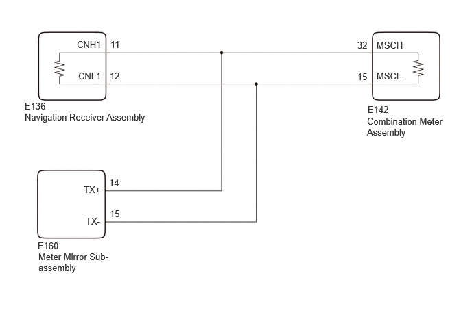
CHECK POINT
When DTC B132187 is output from the combination meter assembly, other ECUs on the same detection circuit may simultaneously output the same DTC depending on the malfunctioning area.
Depending on the combination of DTCs simultaneously output by each ECU, the malfunctioning area can be narrowed down. Refer to the following table for DTC combinations output by each ECU.
| DTC Output Pattern | DTC Output Part Name
(Display on GTS) |
Malfunction Status/Suspected Area | ||
|---|---|---|---|---|
| Combination Meter Assembly
(Combination Meter) |
Navigation Receiver Assembly
(Navigation System) |
Meter Mirror Sub-assembly
(Headup Display) |
||
| 1 | B132187 | U11D087
U11D187 |
B132187 | Short in the Circuit
·
Harness or connector ·
Navigation receiver assembly ·
Meter mirror sub-assembly ·
Combination meter assembly Open in the Circuit
·
Harness or connector ·
Navigation receiver assembly |
| 2 | B132187 | U11D087 | Not output | ·
Harness or connector ·
Combination meter assembly |
| 3 | B132187 | Not output | B132187 | Navigation receiver assembly |
| 4 | B132187 | Not output | Not output | Combination meter assembly |
CAUTION / NOTICE / HINT
- NOTICE:
- ·
When replacing the combination meter assembly, always replace it with a new one. If a combination meter assembly which was installed to another vehicle is used, the information stored in it will not match the information from the vehicle and a DTC may be stored.
·When replacing the combination meter assembly, update the ECU security key.
·After the ignition switch is turned off, there may be a waiting time before disconnecting the negative (-) auxiliary battery terminal.
·If the power source circuit for any of the following ECUs is malfunctioning, DTCs may not be correctly output. Therefore, before performing troubleshooting using the following procedure, perform inspections related to the power source circuit of each ECU.
--Meter mirror sub-assembly
-
PROCEDURE
Check each system for DTCs.
- Body Electrical > Combination Meter > Trouble Codes
- 50001 409
- Body Electrical > Navigation System > Trouble Codes
- 50001 496
- Body Electrical > Head Up Display > Trouble Codes
- 50001 408
Confirm the DTC combinations of the following table.
| DTC Output Pattern | DTC Output Part Name
(Display on GTS) |
||
|---|---|---|---|
| Combination Meter Assembly
(Combination Meter) |
Navigation Receiver Assembly
(Navigation System) |
Meter Mirror Sub-assembly
(Headup Display) |
|
| 1 | B132187 | U11D087
U11D187 |
B132187 |
| 2 | B132187 | U11D087 | Not output |
| 3 | B132187 | Not output | B132187 |
| 4 | B132187 | Not output | Not output |
- Result:
Result Proceed to DTC output pattern 1 A DTC output pattern 2 B DTC output pattern 3 C DTC output pattern 4 D
A
B
C
D
Pre-procedure1
Remove 1 of the following ECUs.
Navigation receiver assembly
- HINT:
Meter mirror sub-assembly
- HINT:
Combination meter assembly
- HINT:
Procedure1
Measure the resistance of the removed ECU.
- NOTICE:
- ·
Refer to the following table for the specified conditions of each ECU.
·If the specified conditions are met, repeat the inspection procedure from step (a) for another ECU.
- HINT:
-
If the results of an ECU are not as specified, it is suspected that the ECU is the cause of the DTC.
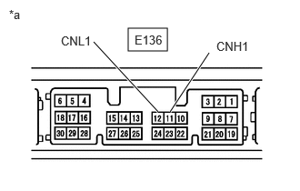
| *a | Component without harness connected
(Navigation Receiver Assembly) |
Inspect the navigation receiver assembly.
- Standard Resistance:
Tester Connection Condition Specified Condition Click Location & Routing(E136)Location & Routingewd_type=routing;type=c;code=E136
Click Connector(E136)Instrument Panel>Instrument Panel Wire / Telephone Computer Wire>Navigation Receiver Assemblyewd_type=component;type=c;code=E136;pinno=11,12
E136-11 (CNH1) - E136-12 (CNL1) Always 108 to 132 Ω
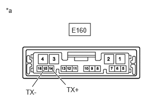
| *a | Component without harness connected
(Meter Mirror Sub-assembly) |
Inspect the meter mirror sub-assembly.
- Standard Resistance:
Tester Connection Condition Specified Condition Click Location & Routing(E160)Location & Routingewd_type=routing;type=c;code=E160
Click Connector(E160)Instrument Panel>Instrument Panel Wire / Telephone Computer Wire>Meter Mirror Sub-Assemblyewd_type=component;type=c;code=E160;pinno=14,15
E160-14 (TX+) - E160-15 (TX-) Always 200 Ω or higher
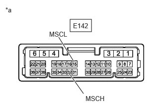
| *a | Component without harness connected
(Combination Meter Assembly) |
Inspect the combination meter assembly.
- Standard Resistance:
Tester Connection Condition Specified Condition Click Location & Routing(E142)Location & Routingewd_type=routing;type=c;code=E142
Click Connector(E142)Instrument Panel>Instrument Panel Wire / Telephone Computer Wire>Combination Meter Assemblyewd_type=component;type=c;code=E142;pinno=32,15
E142-32 (MSCH) - E142-15 (MSCL) Always 108 to 132 Ω
- Result:
Result Proceed to The results of all ECUs are as specified A The results of the navigation receiver assembly are not as specified B The results of the meter mirror sub-assembly are not as specified C The results of the combination meter assembly are not as specified D
Post-procedure1
None
A
B
C
D
Pre-procedure1
Disconnect the cable from the negative (-) auxiliary battery terminal.
Disconnect the E142 combination meter assembly connector.
Procedure1
Measure the resistance according to the value(s) in the table below.
- Standard Resistance:
Tester Connection Condition Specified Condition Click Location & Routing(E142)Location & Routingewd_type=routing;type=c;code=E142
Click Connector(E142)Instrument Panel>Instrument Panel Wire / Telephone Computer Wire>Combination Meter Assemblyewd_type=component;type=c;code=E142;pinno=32,15
E142-32 (MSCH) - E142-15 (MSCL) Cable disconnected from negative (-) auxiliary battery terminal 108 to 132 Ω
- Result:
Proceed to OK NG
Post-procedure1
None
OK
NG