M20C-FKS, M20D-FKS FUEL FUEL MAIN VALVE REMOVAL
CAUTION / NOTICE / HINT
The necessary procedures (adjustment, calibration, initialization or registration) that must be performed after parts are removed and installed, or replaced during fuel main valve assembly removal/installation are shown below.
| Replaced Part or Performed Procedure | Necessary Procedure | Effect/Inoperative Function when Necessary Procedure not Performed | Link |
|---|---|---|---|
| Battery terminal is disconnected/reconnected | Reset back door close position | Power Back Door System | ( 202111,999999,_59,_111831,_0505274,RM100000001ZMEG,) 202111,999999,_59,_111831,_0505274,RM100000001ZMEG,)
|
- CAUTION:
- ·
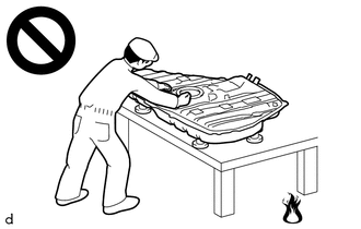
Never perform work on fuel system components near any possible ignition sources.
·Vaporized fuel could ignite, resulting in a serious accident.
·
Do not perform work on fuel system components without first disconnecting the cable from the negative (-) battery terminal.
·Sparks could cause vaporized fuel to ignite, resulting in a serious accident.
- NOTICE:
-
 2.031,1.271 2.615,0.958 2.615,0.958 2.854,0.958 true 2.885,0.865 3.198,1.063 0.313,0.198 10 false *a
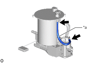
*a Tube
-
Do not disconnect the tube shown in the illustration when disassembling the fuel suction tube with pump and gauge assembly. Doing so will cause reassembly of the fuel suction tube with pump and gauge assembly to be impossible as the tube is pressed into the fuel suction plate sub-assembly.
- HINT:
-
When the cable is disconnected / reconnected to the battery terminal, systems temporarily stop operating. However, each system has a function that completes learning the first time the system is used.
Items for which learning is completed by driving the vehicle Effect/Inoperative Function when Necessary Procedure not Performed Necessary Procedure Link Lane Tracing Assist System Drive the vehicle straight ahead at 15 km/h (10 mph) or more for 1 seconds or more. ( 202111,999999,_95,_111850,_0502173,RM100000001Z92I,)
Pre-collision System Stop and Start System Idle the engine for approximately 5 to 60 minutes or drive the vehicle until stop and start control is permitted ( 202406,999999,_51,_111803,_0509671,RM100000002KOGF,)
Items for which learning is completed by operating the vehicle normally Effect/Inoperative Function when Necessary Procedure not Performed Necessary Procedure Link Power Door Lock Control System
·Back door opener
Perform door unlock operation with door control switch or electrical key transmitter sub-assembly switch. ( 202111,999999,_58,_111830,_0505351,RM100000001ZMT3,)
Air Conditioning System After the ignition switch is turned to ON, the servo motor standard position is recognized. -
PROCEDURE

 77103
1.REMOVE FUEL SUB-TANK SUB-ASSEMBLY
77103
1.REMOVE FUEL SUB-TANK SUB-ASSEMBLY
23070
2.REMOVE FUEL MAIN VALVE ASSEMBLY
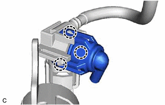
Disengage the 3 claws and remove the No. 3 fuel suction support from the fuel suction tube with pump and gauge assembly.
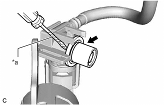
| *a | Protective Tape |
Using a screwdriver with its tip wrapped with protective tape, remove the fuel main valve assembly from the fuel suction tube with pump and gauge assembly.
- NOTICE:
- ·
Pull out the fuel main valve assembly carefully because the O-ring is firmly installed between the fuel main valve assembly and fuel suction tube with pump and gauge assembly.
·Do not damage the fuel suction tube with pump and gauge assembly.
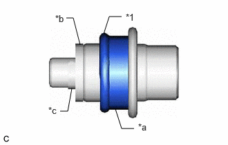
| *1 | O-ring |
| *a | Spacer |
| *b | Mesh |
| *c | Mini-clip |
Remove the O-ring and spacer from the fuel main valve assembly.
- NOTICE:
-
Do not remove the mesh and mini-clip from the fuel main valve assembly.