AXLE AND DIFFERENTIAL DIFFERENTIAL MOUNT CUSHION REMOVAL
CAUTION / NOTICE / HINT
The necessary procedures (adjustment, calibration, initialization, or registration) that must be performed after parts are removed and installed, or replaced during rear No. 1 differential mount cushion removal/installation are shown below.
| Replaced Part or Performed Procedure | Necessary Procedure | Effect/Inoperative Function when Necessary Procedure not Performed | Link |
|---|---|---|---|
|
*1: Also necessary after performing a tire rotation. *2: It is not necessary to perform this procedure if the tire pressure warning valve and transmitters are installed to the same location. *3: The vehicle height changes because of suspension or tire replacement. |
|||
| Tires | ·
Initialization*1*2 ·
Tire Position Identification*1*2 |
Tire Pressure Warning System | Refer to Procedures Necessary When Replacing Parts (for Tire Pressure Warning System)
(  202406,202409,_V1,_111780,_0504977,RM100000002MO96,202409,999999,_V1,_111780,_0504977,RM100000002OMBP,) 202406,202409,_V1,_111780,_0504977,RM100000002MO96,202409,999999,_V1,_111780,_0504977,RM100000002OMBP,)
|
| Rear wheel alignment adjustment | ·
Perform reset memory ·
Perform "Calibration" |
·
DTCs are stored ·
ABS warning light illuminates ·
Slip indicator light illuminates ·
Electronically controlled brake system does not operate correctly |
(202203,999999,_54,_111814,_0500728,RM1000000022HI0,)
|
| Suspension parts*3 | Parking assist ECU initialization | Panoramic View Monitor System | (202406,202409,_56,_111825,_0694611,RM100000002LT4S,202409,999999,_56,_111825,_0500432,RM100000002O1F6,)
|
| Rear television camera assembly optical axis (Back camera position setting) | Parking Assist Monitor System | (202406,202409,_56,_111825,_0524148,RM100000002KP56,202409,999999,_56,_111825,_0524148,RM100000002OUWG,)
|
|
| Gas leaks from exhaust system | Inspection After Repair | ·
Poor idle, etc. ·
Engine start function, etc. |
(202303,999999,_51,_111785,_0504416,RM1000000029BFF,)
|
CAUTION / NOTICE / HINT
- CAUTION:
-
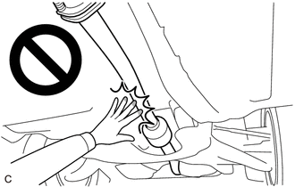
-
To prevent burns, do not touch the engine, exhaust pipe or other high temperature components while the engine is hot.
PROCEDURE

 1.REMOVE REAR DIFFERENTIAL CARRIER ASSEMBLY
58327B
2.REMOVE MAIN MUFFLER HEAT INSULATOR
48812
3.REMOVE REAR STABILIZER BAR
41651G
4.REMOVE DIFFERENTIAL MOUNT CUSHION
Using SST, remove the differential mount cushion.
- SST
- 09316-12010
09570-24011
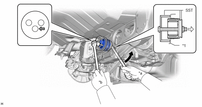
| *1 | Rear Suspension Member Sub-assembly | - | - |
| *a | Turn | *b | Hold |

|
Turning Direction | 
|
Front of Vehicle |

|
SST Bolt Position | - | - |
- NOTICE:
- ·
Do not bring SST into contact with the rear suspension member sub-assembly.
·Before using SST, apply grease to SST bolt.
·Set SST in the correct direction.
·Do not tilt the bolt of SST.
·Do not reuse the differential mount cushion.