AXLE AND DIFFERENTIAL REAR AXLE HUB BOLT REPLACEMENT
CAUTION / NOTICE / HINT
The necessary procedures (adjustment, calibration, initialization, or registration) that must be performed after parts are removed and installed, or replaced during rear axle hub bolt removal/installation are shown below.
| Replaced Part or Performed Procedure | Necessary Procedure | Effect/Inoperative Function when Necessary Procedure not Performed | Link |
|---|---|---|---|
|
*1: Also necessary after performing a tire rotation. *2: It is not necessary to perform this procedure if the tire pressure warning valve and transmitters are installed to the same location. |
|||
for HV Model
Auxiliary battery terminal is disconnected/reconnected |
Reset back door close position | Power Back Door System | ( 202111,999999,_59,_111831,_0505274,RM100000001ZMEG,) 202111,999999,_59,_111831,_0505274,RM100000001ZMEG,)
|
| Tires | ·
Initialization*1*2 ·
Tire Position Identification*1*2 |
Tire Pressure Warning System | Refer to Procedures Necessary When Replacing Parts (for Tire Pressure Warning System)
( 202406,202409,_V1,_111780,_0504977,RM100000002MO96,202409,999999,_V1,_111780,_0504977,RM100000002OMBP,)
|
- HINT:
- for HV Model:
-
When the cable is disconnected / reconnected to the auxiliary battery terminal, systems temporarily stop operating. However, each system has a function that completes learning the first time the system is used.
Items for which learning is completed by driving the vehicle Effect/Inoperative Function when Necessary Procedure not Performed Necessary Procedure Link Lane Tracing Assist System Drive the vehicle straight ahead at 35 km/h (22 mph) or more for 5 seconds or more. ( 202111,999999,_95,_111850,_0502173,RM100000001Z92I,)
Pre-collision System
Items for which learning is completed by operating the vehicle normally Effect/Inoperative Function when Necessary Procedure not Performed Necessary Procedure Link Power Door Lock Control System
·Back door opener
Perform door unlock operation with door control switch or electrical key transmitter sub-assembly switch. ( 202111,999999,_58,_111830,_0505351,RM100000001ZMT3,)
Air Conditioning System After the ignition switch is turned to ON, the servo motor standard position is recognized. -
CAUTION / NOTICE / HINT
- NOTICE:
- ·
When removing or installing the rear disc brake caliper assembly, pushing back the disc brake piston may cause a large clearance between the brake pads and brake disc. When the brake pedal is depressed with a large clearance between the brake pads and the brake disc, DTC C140000 and/or C140A00 related to abnormal brake fluid pressure may be stored. Make sure to clear any DTCs after performing this procedure. (for HV Model)
·While the auxiliary battery is connected, even if the ignition switch is off, the brake control system activates when the brake pedal is depressed or any door courtesy switch turns on. Therefore, when servicing the brake system components, do not operate the brake pedal or open/close the doors while the auxiliary battery is connected. (for HV Model)
- HINT:
- ·
Use the same procedure for the RH and LH sides.
·The following procedure is for the LH side.
PROCEDURE

 1. PRECAUTION
- NOTICE:
- ·
After the ignition switch is turned off, there may be a waiting time before disconnecting the negative (-) auxiliary battery terminal. (for HV Model)
·Make sure to read the precautions of the electric parking brake system before removing the rear brake assembly.
2.DISABLE BRAKE CONTROL (for HV Model)
3.REMOVE REAR WHEEL
890C0A
4.DISCONNECT NO. 2 PARKING BRAKE WIRE ASSEMBLY
5.SEPARATE REAR DISC BRAKE CALIPER ASSEMBLY
Remove the 2 bolts and separate the rear disc brake caliper assembly from the rear axle carrier sub-assembly.
- NOTICE:
-
Use wire or an equivalent tool to keep the rear disc brake caliper assembly from hanging by the rear flexible hose.
42431
6.REMOVE REAR DISC
42312E
7.REMOVE REAR AXLE HUB BOLT
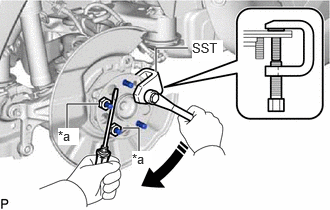
| *a | Service Nut |
Temporarily install 2 service nuts to the rear axle hub bolts as shown in the illustration.
- Recommended service nut:
Thread diameter: 12.0 mm (0.472 in.)
Thread pitch: 1.5 mm (0.0591 in.)
- NOTICE:
-
Install the service nuts to prevent damage to the rear axle hub bolts.
Using SST and a screwdriver or an equivalent tool to hold the rear axle hub and bearing assembly, remove the rear axle hub bolt.
- SST
- 09611-12010
- NOTICE:
-
Do not damage the threads of the rear axle hub bolts.
42312E
8.INSTALL REAR AXLE HUB BOLT
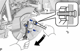
| *a | Service Nut |
| *b | Washer |
Temporarily install a new rear axle hub bolt to the rear axle hub and bearing assembly.
Install a washer and service nut to the rear axle hub bolt as shown in the illustration.
- Recommended service nut:
Thread diameter: 12.0 mm (0.472 in.)
Thread pitch: 1.5 mm (0.0591 in.)
- HINT:
-
Recommended washer thickness is 5 mm (0.197 in.) or more.
Using a screwdriver or an equivalent tool to hold the rear axle hub and bearing assembly, install the rear axle hub bolt by tightening the service nut.
- NOTICE:
- ·
Install the service nuts to prevent damage to the rear axle hub bolts.
·Do not damage the threads of the rear axle hub bolts.
Remove the 3 service nuts and washer from the 3 rear axle hub bolts.
42431
9.INSTALL REAR DISC
10.INSTALL REAR DISC BRAKE CALIPER ASSEMBLY
Install the rear disc brake caliper assembly to the rear axle carrier sub-assembly with the 2 bolts.
- Torque:
- 107 N*m (1091 kgf*cm, 79 ft.*lbf)
890C0A
11.CONNECT NO. 2 PARKING BRAKE WIRE ASSEMBLY
12.INSTALL REAR WHEEL
13.CONNECT CABLE TO NEGATIVE AUXILIARY BATTERY TERMINAL (for HV Model)
14. INITIALIZATION AFTER RECONNECTING AUXILIARY BATTERY TERMINAL (for HV Model)
- HINT:
-
When disconnecting and reconnecting the auxiliary battery, there is an automatic learning function that completes learning when the respective system is used.