M20C-FKS, M20D-FKS ENGINE CONTROL SFI SYSTEM Fuel Pump Control Circuit
DESCRIPTION
The fuel pump (for low pressure side) circuit consists of the ECM, fuel pump (for low pressure side) and fuel pump control ECU (which operates the fuel pump (for low pressure side)). Based on the engine output, the ECM determines the fuel pump speed. The speed is then converted to a duty signal and sent to the fuel pump control ECU. Based on the signal sent from the ECM, the fuel pump control ECU adjusts the fuel pump (for low pressure side) operation speed.
WIRING DIAGRAM
CAUTION / NOTICE / HINT
- NOTICE:
-
Inspect the fuses for circuits related to this system before performing the following procedure.
PROCEDURE
Check around and beneath the vehicle for fuel leaks, fumes, etc.
- OK:
No fuel leaks present.
- Result:
Proceed to OK NG
OK
NG
Check whether the fuel pump operating sound occurs when performing the Active Test on the GTS.
- Powertrain > Engine > Active Test
-
Tester Display Activate the Circuit Relay (Brushless) - 50004 372 40
- Standard:
GTS Operation Standard ON Operating sounds can be heard from fuel pump (for low pressure side)
- Result:
Proceed to OK NG
OK
NG
Install the fuel pressure gauge (for low pressure line of low pressure side).
Compare the values in the Data List using the GTS and the fuel pressure gauge when the Active Test was performed.
- Powertrain > Engine > Active Test
-
Active Test Display Control the Fuel Pump Duty Ratio (Brushless) -
Data List Display Fuel Pressure (Low) / Fuel Pressure 2 - 50004 372 39 267
- Standard:
GTS Operation Standard Low Data List value and fuel pressure gauge are within +/-50 kPag of each other High
- HINT:
-
Perform "Inspection After Repair" after replacing the No. 2 fuel pressure sensor (for low pressure side).
- Result:
Proceed to OK NG
OK
NG
Read the values displayed on the GTS while the engine is cranking.
- Powertrain > Engine > Data List
-
Tester Display Target Fuel Pressure (Low) / Target Fuel Pressure 2 Fuel Pressure (Low) / Fuel Pressure 2 Low Fuel Pressure Sensor - 50003 372 266,267,545
- Result:
Result Proceed to Low Fuel Pressure Sensor value is within +/- 65 kPag of the Target Fuel Pressure (Low) / Target Fuel Pressure 2 A Low Fuel Pressure Sensor value is more than 65 kPag higher than the target fuel pressure (low) / Target Fuel Pressure 2 B Low Fuel Pressure Sensor value is more than 65 kPag lower than the target fuel pressure (low) / Target Fuel Pressure 2 C
A
B
- HINT:
-
Relief blockage such as clogging of the jet pump is suspected.
C
Install the fuel pressure gauge (for low pressure line of low pressure side).
Start the engine.
Measure the fuel pressure at idle.
- Standard Fuel Pressure:
196 to 833 kPa (2.0 to 8.5 kgf/cm2, 28 to 121 psi)
- HINT:
-
Refer to Standard Idle Speed.
Stop the engine.
Check that the fuel pressure remains as specified for 5 minutes.
- Standard Fuel Pressure:
98 kPa (1.0 kgf/cm2, 14.2 psi) or more
- HINT:
-
Perform "Inspection After Repair" after replacing the fuel pump (for low pressure side).
- Result:
Proceed to OK NG
OK
- HINT:
-
If the difference between Target Fuel Pressure (Low) / Target Fuel Pressure 2 and Low Fuel Pressure Sensor is more than 200 kPa in the freeze frame data of DTC P008700 and the malfunctioning part could not be identified, replace the fuel pump (for low pressure side) as the fuel supply system, which cannot reproduce symptoms easily, may be malfunctioning.
NG
Check the amount of fuel remaining.
- HINT:
- ·
No fuel remains in the fuel tank: Malfunction of the fuel sender gauge assembly is suspected.
·Only the fuel pump side fuel chamber has no fuel remaining: Malfunction of the jet pump is suspected.
·Fuel remains in the fuel tank: Malfunction of the fuel pump (for low pressure side) is suspected.
·Perform "Inspection After Repair" after replacing the fuel pump (for low pressure side).
- Result:
Proceed to NEXT
NEXT
Disconnect the fuel pump (for low pressure side) connector.
Operate the fuel pump control ECU using the Active Test function and measure the voltage according to the value(s) in the table below.
- Powertrain > Engine > Active Test
-
Tester Display Fuel Pump Single Phase Energization - 50004 372 49
Operate the fuel pump control ECU using the Active Test function and measure the voltage according to the value(s) in the table below.
- Standard Voltage:
Tester Connection GTS Operation Specified Condition Click Location & Routing(L22)Location & Routingewd_type=routing;type=c;code=L22
Click Connector(L22)Body>No. 2 Floor Wire>Fuel Suction Tube with Pump and Gage Assemblyewd_type=component;type=c;code=L22;pinno=3,4,2
L22-3 (BLPU) - Body ground U Phase 4.4 to 8.4 V* L22-4 (BLPV) - Body ground V Phase 4.4 to 8.4 V* L22-2 (BLPW) - Body ground W Phase 4.4 to 8.4 V*
- HINT:
- ·
*: This Active Test restricts the fuel pump control ECU output duty cycle to 50%. Therefore, the output voltage of the fuel pump control ECU will be approximately 50% of the power source voltage.
·Before performing this inspection, check that the battery voltage is between 11 and 14 V (not depleted).
·Perform "Inspection After Repair" after replacing the fuel pump (for low pressure side).
- Result:
Proceed to OK NG
OK
NG
Disconnect the fuel pump control ECU connector.
Disconnect the fuel pump (for low pressure side) connector.
Measure the resistance according to the value(s) in the table below.
- Standard Resistance:
Tester Connection Condition Specified Condition Click Location & Routing(L11,L22)Location & Routingewd_type=routing;type=c,c;code=L11,L22
Click Connector(L11)Body>No. 2 Floor Wire>Fuel Pump Control ECUewd_type=component;type=c;code=L11;pinno=2,3,4
Click Connector(L22)Body>No. 2 Floor Wire>Fuel Suction Tube with Pump and Gage Assemblyewd_type=component;type=c;code=L22;pinno=3,4,2
L11-2 (FPU) - L22-3 (BLPU) Always Below 1 Ω L11-3 (FPV) - L22-4 (BLPV) Always Below 1 Ω L11-4 (FPW) - L22-2 (BLPW) Always Below 1 Ω L11-2 (FPU) or L22-3 (BLPU) - Body ground and other terminals Always 10 kΩ or higher L11-3 (FPV) or L22-4 (BLPV) - Body ground and other terminals Always 10 kΩ or higher L11-4 (FPW) or L22-2 (BLPW) - Body ground and other terminals Always 10 kΩ or higher
- Result:
Proceed to OK NG
- HINT:
-
Perform "Inspection After Repair" after replacing the fuel pump (for low pressure side).
OK
NG
Disconnect the fuel pump control ECU connector.
Turn the ignition switch to ON.
Measure the voltage according to the value(s) in the table below.
- Standard Voltage:
Tester Connection Switch Condition Specified Condition Click Location & Routing(L12)Location & Routingewd_type=routing;type=c;code=L12
Click Connector(L12)Body>No. 2 Floor Wire>Fuel Pump Control ECUewd_type=component;type=c;code=L12;pinno=1,3
L12-1 (+B) - L12-3 (GND) Ignition switch ON 11 to 14 V
- Result:
Proceed to OK NG
OK
NG
Disconnect the fuel pump control ECU connector.
Operate the fuel pump control ECU using the Active Test function and measure the resistance according to the value(s) in the table below.
- Powertrain > Engine > Active Test
-
Tester Display Fuel Pump Single Phase Energization - 50004 372 49
- Standard Resistance:
Tester Connection GTS Operation Specified Condition Click Location & Routing(L12)Location & Routingewd_type=routing;type=c;code=L12
Click Connector(L12)Body>No. 2 Floor Wire>Fuel Pump Control ECUewd_type=component;type=c;code=L12;pinno=2
L12-2 (FPC) - Body ground Before Active Test → During Active Test Before Active Test: Resistance is stable → During Active Test: Resistance fluctuates*
- HINT:
-
*: Using the Active Test, duty control of the transistors in the ECM will be performed. Due to the duty control, resistance of the FPC terminal will be unstable during the Active Test. If the resistance is stable before the Active Test and fluctuates while performing the Active Test, it can be determined that the transistor is operating. If the transistor does not operate during the Active Test, the ECM may be malfunctioning.
- Result:
Proceed to OK NG
OK
NG
Disconnect the fuel pump control ECU connector.
Disconnect the ECM connector.
Measure the resistance according to the value(s) in the table below.
- Standard Resistance:
Tester Connection Condition Specified Condition Click Location & Routing(L12,A109)Location & Routingewd_type=routing;type=c,c;code=L12,A109
Click Connector(L12)Body>No. 2 Floor Wire>Fuel Pump Control ECUewd_type=component;type=c;code=L12;pinno=2
Click Connector(A109)Engine Compartment>Engine Room Main Wire / Transmission Wire>ECMewd_type=component;type=c;code=A109;pinno=61
L12-2 (FPC) - A109-61 (FPC) Always Below 1 Ω L12-2 (FPC) or A109-61 (FPC) - Body ground and other terminals Always 10 kΩ or higher
- Result:
Proceed to OK NG
OK
NG
Disconnect the fuel pump control ECU connector.
Measure the resistance according to the value(s) in the table below.
- Standard Resistance:
Tester Connection Condition Specified Condition Click Location & Routing(L12)Location & Routingewd_type=routing;type=c;code=L12
Click Connector(L12)Body>No. 2 Floor Wire>Fuel Pump Control ECUewd_type=component;type=c;code=L12;pinno=3
L12-3 (GND) - Body ground Always Below 1 Ω
- Result:
Proceed to OK NG
OK
NG
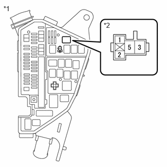
| *1 | No. 1 Engine Room Relay Block and No. 1 Junction Block Assembly |
| *2 | EFI-MAIN NO. 2 Relay |
Remove the EFI-MAIN NO. 2 relay from the No. 1 engine room relay block and No. 1 junction block assembly.
Measure the voltage according to the value(s) in the table below.
- Standard Voltage:
Tester Connection Condition Specified Condition 3 (EFI-MAIN NO. 2 relay) - Body ground Always 11 to 14 V
- Result:
Proceed to OK NG
OK
NG
- Result:
Proceed to OK NG
OK
NG
Remove the EFI-MAIN NO. 1 and EFI-MAIN NO. 2 relay from the No. 1 engine room relay block and No. 1 junction block assembly.
Remove the VVT relay, D INJ relay and EFI-MAIN NO. 3 relay from the No. 1 engine room relay block and No. 1 junction block assembly.
- HINT:
-
Remove the VVT relay, D INJ relay and EFI-MAIN NO. 3 relay connected between the checked terminals as the coil inside the relay influences the measurement value.
Measure the resistance according to the value(s) in the table below.
- Standard Resistance:
Tester Connection Condition Specified Condition 5 (EFI-MAIN NO. 1 relay) - 1 (EFI-MAIN NO. 2 relay) Always Below 1 Ω 5 (EFI-MAIN NO. 1 relay) or 1 (EFI-MAIN NO. 2 relay) - Body ground and other terminals Always 10 kΩ or higher
- Result:
Proceed to OK NG
OK
NG
Remove the EFI-MAIN NO. 2 relay from the No. 1 engine room relay block and No. 1 junction block assembly.
Measure the resistance according to the value(s) in the table below.
- Standard Resistance:
Tester Connection Condition Specified Condition 2 (EFI-MAIN NO. 2 relay) - Body ground Always Below 1 Ω
- Result:
Proceed to OK NG
OK
NG
Remove the EFI-MAIN NO. 2 relay from the No. 1 engine room relay block and No. 1 junction block assembly.
Measure the resistance according to the value(s) in the table below.
- Standard Resistance:
Tester Connection Condition Specified Condition Click Location & Routing(L12)Location & Routingewd_type=routing;type=c;code=L12
Click Connector(L12)Body>No. 2 Floor Wire>Fuel Pump Control ECUewd_type=component;type=c;code=L12;pinno=1
5 (EFI-MAIN NO. 2 relay) - L12-1 (+B) Always Below 1 Ω 5 (EFI-MAIN NO. 2 relay) or L12-1 (+B) - Body ground and other terminals Always 10 kΩ or higher
- Result:
Proceed to OK NG
OK
NG