M20C-FKS, M20D-FKS ENGINE CONTROL SFI SYSTEM ECM Power Source Circuit
DESCRIPTION
When the ignition switch turned to ON, the battery voltage is applied to IGSW of the ECM. When the transistor in the MREL circuit operates, current flows from the battery to ground through the drive circuit of the EFI-MAIN NO. 1 relay, thus operating the relay which supplies power to the +B and +B2 terminals of the ECM.
WIRING DIAGRAM
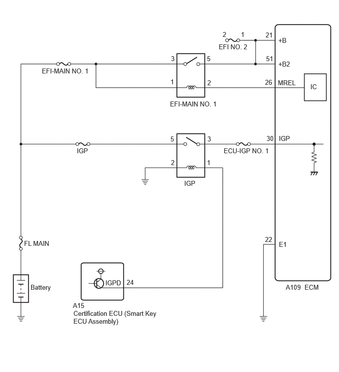
CAUTION / NOTICE / HINT
- NOTICE:
-
Inspect the fuses for circuits related to this system before performing the following procedure.
PROCEDURE
Disconnect the ECM connector.
Measure the resistance according to the value(s) in the table below.
- Standard Resistance:
Tester Connection Condition Specified Condition Click Location & Routing(A109)Location & Routingewd_type=routing;type=c;code=A109
Click Connector(A109)Engine Compartment>Engine Room Main Wire / Transmission Wire>ECMewd_type=component;type=c;code=A109;pinno=22
A109-22 (E1) - Body ground Always Below 1 Ω
- Result:
Proceed to OK NG
OK
NG
Disconnect the ECM connector.
Turn the ignition switch to ON.
Measure the voltage according to the value(s) in the table below.
- Standard Voltage:
Tester Connection Condition Specified Condition Click Location & Routing(A109)Location & Routingewd_type=routing;type=c;code=A109
Click Connector(A109)Engine Compartment>Engine Room Main Wire / Transmission Wire>ECMewd_type=component;type=c;code=A109;pinno=30
A109-30 (IGP) - Body ground Ignition switch ON 11 to 14 V
- Result:
Proceed to OK NG
OK
NG
- Result:
Proceed to OK NG
OK
NG
Remove the VVT relay, D INJ relay, EFI-MAIN NO. 2 relay and EFI-MAIN NO. 3 relay from the No. 1 engine room relay block and No. 1 junction block assembly.
- HINT:
-
Remove the VVT relay, D INJ relay, EFI-MAIN NO. 2 relay and EFI-MAIN NO. 3 relay connected between the checked terminals as the coil inside the relay influences the measurement value.
Disconnect the ECM connector.
Measure the resistance according to the value(s) in the table below.
- Standard Resistance:
Tester Connection Condition Specified Condition Click Location & Routing(A109)Location & Routingewd_type=routing;type=c;code=A109
Click Connector(A109)Engine Compartment>Engine Room Main Wire / Transmission Wire>ECMewd_type=component;type=c;code=A109;pinno=26,21,51
2 (EFI-MAIN NO. 1 relay) - A109-26 (MREL) Always Below 1 Ω 5 (EFI-MAIN NO. 1 relay) - A109-21 (+B) Always Below 1 Ω 5 (EFI-MAIN NO. 1 relay) - A109-51 (+B2) Always Below 1 Ω 2 (EFI-MAIN NO. 1 relay) or A109-26 (MREL) - Body ground and other terminals Always 10 kΩ or higher 5 (EFI-MAIN NO. 1 relay), A109-21 (+B) or A109-51 (+B2) - Body ground and other terminals Always 10 kΩ or higher
- Result:
Proceed to OK NG
OK
NG
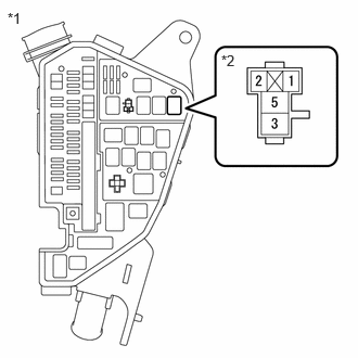
| *1 | No. 1 Engine Room Relay Block and No. 1 Junction Block Assembly |
| *2 | EFI-MAIN NO. 1 Relay |
Remove the EFI-MAIN NO. 1 relay from the No. 1 engine room relay block and No. 1 junction block assembly.
Measure the voltage according to the value(s) in the table below.
- Standard Voltage:
Tester Connection Condition Specified Condition 3 (EFI-MAIN NO. 1 relay) - Body ground Always 11 to 14 V 1 (EFI-MAIN NO. 1 relay) - Body ground Always 11 to 14 V
- Result:
Proceed to OK NG
OK
NG
- Result:
Proceed to OK NG
OK
NG
Remove the IGP relay from the No. 1 engine room relay block and No. 1 junction block assembly.
Disconnect the ECM connector.
Measure the resistance according to the value(s) in the table below.
- Standard Resistance:
Tester Connection Condition Specified Condition Click Location & Routing(A109)Location & Routingewd_type=routing;type=c;code=A109
Click Connector(A109)Engine Compartment>Engine Room Main Wire / Transmission Wire>ECMewd_type=component;type=c;code=A109;pinno=30
3 (IGP relay) - A109-30 (IGP) Always Below 1 Ω 3 (IGP relay) or A109-30 (IGP) - Body ground and other terminals Always 10 kΩ or higher
- Result:
Proceed to OK NG
OK
NG

| *1 | No. 1 Engine Room Relay Block and No. 1 Junction Block Assembly |
| *2 | IGP Relay |
Remove the IGP relay from the No. 1 engine room relay block and No. 1 junction block assembly.
Measure the voltage according to the value(s) in the table below.
- Standard Voltage:
Tester Connection Condition Specified Condition 5 (IGP relay) - Body ground Always 11 to 14 V
- Result:
Proceed to OK NG
OK
NG
Remove the IGP relay from the No. 1 engine room relay block and No. 1 junction block assembly.
Measure the resistance according to the value(s) in the table below.
- Standard Resistance:
Tester Connection Condition Specified Condition 2 (IGP relay) - Body ground Always Below 1 Ω
- Result:
Proceed to OK NG
OK
NG
Disconnect the certification ECU (smart key ECU assembly) connector.
Remove the IGP relay from the No. 1 engine room relay block and No. 1 junction block assembly.
Measure the resistance according to the value(s) in the table below.
- Standard Resistance:
Tester Connection Condition Specified Condition Click Location & Routing(A15)Location & Routingewd_type=routing;type=c;code=A15
Click Connector(A15)Instrument Panel>Engine Room Main Wire>Smart Key ECU Assemblyewd_type=component;type=c;code=A15;pinno=24
A15-24 (IGPD) - 1 (IGP relay) Always Below 1 Ω A15-24 (IGPD) or 1 (IGP relay) - Body ground and other terminals Always 10 kΩ or higher
- Result:
Proceed to OK NG
OK
NG