ADVANCED DRIVER ASSISTANCE SYSTEM PRE-COLLISION SYSTEM HOW TO PROCEED WITH TROUBLESHOOTING
CAUTION / NOTICE / HINT
- HINT:
- ·
Use these procedures to troubleshoot the pre-collision system.
·*: Use the GTS.
PROCEDURE
- Result:
Proceed to NEXT
NEXT
| Pre-collision System Customer Problem Analysis | Vehicle Brought to Workshop | ||||||
|---|---|---|---|---|---|---|---|
| Year | Month | Day | |||||
| Dealer name | Person in charge at headquarters | Telephone number | |||||
| Shop name | Person in charge at shop | ||||||
| Frame type | Frame No. | First registered year | Total distance traveled | ||||
| Customer concerns (Include details) | Does not operate | ||||||
| Operates abnormally | |||||||
| Date of malfunction occurrence (Since when) | Year | Month | Day | Approx. Time | |||
| Date of last inspection | Year | Month | Day | ||||
| Frequency of problem symptoms | Once / Occasionally (times per day, times per month) / Every time certain conditions are met ( ) | ||||||
| Weather | Sunny / Cloudy / Rain / Snow (Amount of snowfall cm) / Other ( ) | Vehicle speed | Approximately ( ) km/h | ||||
| Place | Prefecture/State/Providence
(Attach a map if possible) |
||||||
| Driving path (where vehicle turned, where driver attempted to drive to, etc.)
* Describe the conditions immediately after the occurrence in as much detail as possible. |
Conditions of Occurrence Diagram

|
||||||
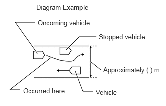
0.771,1.104 0.313,0.458
0.313,0.458 0.719,0.458
true
1.365,1.042 1.646,0.76
1.646,0.76 1.99,0.76
true
0.406,1.854 0.198,1.854
0.198,1.854 1.063,1.177
true
1.875,1.271 2.083,1.438
true
1.563,1.469 1.719,1.885
1.719,1.885 1.927,1.885
true
0.75,0.063 1.99,0.26
1.24,0.198
10
false
Diagram Example
0.781,0.385 3.229,0.583
2.448,0.198
10
false
Oncoming vehicle
2.042,0.677 3.208,1
1.167,0.323
10
false
Stopped vehicle
0.479,1.792 1.406,2.01
0.927,0.219
10
false
Occurred here
1.979,1.823 3.052,2.021
1.073,0.198
10
false
Vehicle
2.135,1.354 3.427,1.604
1.292,0.25
10
false
Approximately ( ) m
|
|||||||
| Surrounding road conditions
Describe whether there were any billboards, metal objects on the road (manholes), guardrails, pipes, cat's eyes, gate bars, etc. |
|||||||
| Urban area / Suburbs / Highway / Other ( ) | Road surface conditions | Temperature | About °C ( °F) | ||||
| Direction of travel | Straight / Right turn / Left turn / Right curve / Left curve | Snow wall(s) | Y / N | ||||
| Driving lane | Number of lanes on one side (lanes) / ( ) lane(s) from left | Backlighting | Y / N | ||||
| Condition of external area around detection sensor | No foreign matter / Foreign matter (water, snow, ice, other) | ||||||
| Additional information about condition of vehicle exterior (other than above) | |||||||
| DTC | First Time (when vehicle brought to workshop) | ||||||
| Second Time (after clearing DTC) | |||||||
| Status of operation switch | Pre-collision system switch | Early / Middle / Late / Off | VSC OFF switch | ON / OFF | |||
| Serial number of main part
* Fill in when removing, installing or replacing part |
Forward recognition camera | ||||||
| Describe the items to the right in as much detail as possible. | Driver operation | Accelerator pedal operated / Brake pedal operated / Steering wheel operated | Time elapsed after hybrid system or engine was started | Approximately ( ) minutes | |||
| Tire pressure inspection result | Front: LH ( ) kPa RH ( ) kPa Standard ( ) kPa | ||||||
| Rear: LH ( ) kPa RH ( ) kPa Standard ( ) kPa | |||||||
| Sensor optical axis inspection result | Forward recognition camera | Accident history | Y / N | ||||
| Millimeter wave radar sensor assembly | Accident history | Y / N | |||||
| Vehicle modified | Y ( ) / N | ||||||
| Items installed or attached around windshield glass | Drive recorder* / Radar detector / Navigation unit (genuine/non-genuine) / ETC / Charms or toys / Other:
*: As information regarding the item is important for the investigation, make sure to obtain the item if permission is given by the customer. |
||||||
- Result:
Proceed to NEXT
NEXT
Measure the auxiliary battery voltage with the ignition switch off.
- Standard voltage:
11 to 14 V
- HINT:
-
If the voltage is below 11 V, recharge or replace the auxiliary battery before proceeding to the next step.
Check the fuses and relays.
Check the connector connections and terminals to make sure that there are no abnormalities such as loose connections, deformation, etc.
- Result:
Proceed to NEXT
NEXT
Check if a pre-collision system warning message is displayed on the multi-information display in the combination meter assembly.
- HINT:
-
If more than one warning message is displayed, check in the order of A, B, C, D and E.
- Result:
Result Proceed to "VSC Turned Off Pre-Collision Brake System Unavailable" is displayed A "Pre-Collision System Malfunction Visit Your Dealer" is displayed B "Pre-Collision System Radar Sensor Blocked Unavailable Clean Radar Sensor" is displayed C Any of the following messages is displayed:
·"Pre-Collision System Unavailable See Owner's Manual"
·"Pre-Collision System Out of Temperature Range Unavailable See Owner's Manual"
·"Pre-Collision System Radar In Self Calibration Unavailable See Owner's Manual"
·"Front Camera Out of Temperature Range Unavailable Wait until Normal Temperature"
·"Front Camera Low Visibility Unavailable See Owner's Manual"
·"Front Camera Unavailable See Owner's Manual"
D Pre-collision system warning message is not displayed E
A
B
C
D
E
Using the GTS, check for CAN communication system DTCs.
for Gasoline Model: Click herePower Source / Network>NETWORKING>CAN COMMUNICATION SYSTEM (for Gasoline Model)>DIAGNOSIS SYSTEM202303,202406,_57,_111829,_0499998,RM10000000291NB,202406,202409,_57,_111829,_0499998,RM100000002L89Q,202409,999999,_57,_111829,_0499998,RM100000002O6WO,
- Result:
Result Proceed to CAN DTCs are not output A CAN DTCs are output B
A
B
for HV Model: Click herePower Source / Network>NETWORKING>CAN COMMUNICATION SYSTEM (for HV Model)>HOW TO PROCEED WITH TROUBLESHOOTING202303,999999,_57,_111829,_0501336,RM100000002AL7W,
for Gasoline Model: Click herePower Source / Network>NETWORKING>CAN COMMUNICATION SYSTEM (for Gasoline Model)>HOW TO PROCEED WITH TROUBLESHOOTING202303,999999,_57,_111829,_0499998,RM10000000291N8,
Check for DTCs.
- Body Electrical > Pre-Collision System > Trouble Codes
- 50001 432
- Result:
Result Proceed to DTCs are not output A DTC (C142571) is output B A DTC other than (C142571) is output C
A
B
C
Using the GTS, check for Vehicle Control History (RoB).
- Body Electrical > Pre-Collision System > Utility
-
Tester Display Vehicle Control History (RoB) - 50005 432 55
If the Vehicle Control History (RoB) is output, record it.
- Result:
Result Proceed to Vehicle control history is not output A Vehicle control history (X2013, X2015, X2022, X2025, X2026 or X2028) is output B Vehicle control history other than (X2013, X2015, X2022, X2025, X2026 and X2028) is output C
A
B
C
Using the GTS, clear the Vehicle Control History (RoB).
- Body Electrical > Pre-Collision System > Utility
-
Tester Display Vehicle Control History (RoB) - 50005 432 55
Using the GTS, check for Vehicle Control History (RoB).
- Body Electrical > Pre-Collision System > Utility
-
Tester Display Vehicle Control History (RoB) - 50005 432 55
- Result:
Result Proceed to Vehicle Control History (RoB) is not output A Vehicle Control History (RoB) is output B
A
B
Using the GTS, clear the DTCs.
- Body Electrical > Pre-Collision System > Clear DTCs
- 50002 432
Reproduce the vehicle conditions that were present when the DTCs that were noted were stored.
- HINT:
-
Refer to each corresponding DTC for details on the detection conditions.
Using the GTS, check if the DTCs are output again.
- Body Electrical > Pre-Collision System > Trouble Codes
- 50001 432
- Result:
Result Proceed to DTCs are not output A DTCs are output B
A
B
Check whether the millimeter wave radar sensor assembly and surrounding area is dirty or obstructed by foreign matter.
- HINT:
-
Check that the following situations do not occur.
- ·
A non-genuine radar sensor cover is installed
·The millimeter wave radar sensor assembly or radar sensor cover and its surrounding area are dirty
·An accessory, such as bull bars, a grille guard, etc., which interferes with millimeter radio waves is installed
·The radar sensor cover or its surrounding area has been painted or has a sticker attached
·There is foreign matter attached to or between the radar sensor cover or millimeter wave radar sensor assembly
Clean away any dirt or foreign matter that is adhering to the area around the millimeter wave radar sensor assembly.
- Result:
Proceed to NEXT
NEXT
- NOTICE:
-
Before inspecting the multi-information display, be sure to first turn the ignition switch off and then to ON again.
Turn the ignition switch off.
Turn the ignition switch to ON.
Check whether "Pre-Collision System Radar Sensor Blocked Unavailable Clean Radar Sensor" is displayed on the multi-information display.
- Result:
Result Proceed to Not displayed A Displayed B
A
B
Triangle Target: Click hereADAS / AD>ADVANCED DRIVER ASSISTANCE SYSTEM>MILLIMETER WAVE RADAR SENSOR>TARGET ADJUSTMENT(TRIANGLE TARGET)202303,999999,_95,_111850,_0502179,RM10000000292SE,
Flat Surface Target: Click hereADAS / AD>ADVANCED DRIVER ASSISTANCE SYSTEM>MILLIMETER WAVE RADAR SENSOR>TARGET ADJUSTMENT(FLAT SURFACE TARGET)202303,999999,_95,_111850,_0502179,RM10000000292SF,
Driving Adjustment: Click hereADAS / AD>ADVANCED DRIVER ASSISTANCE SYSTEM>MILLIMETER WAVE RADAR SENSOR>DRIVING ADJUSTMENT202303,999999,_95,_111850,_0502179,RM10000000292SD,
Using the GTS, read the following Data List item for the front radar system.
- Body Electrical > Front Radar Sensor > Data List
-
Tester Display Measurement Item Range Normal Condition Diagnostic Note On-Line Calibration Angle (Horizontal) Calibrated angle value (horizontal) -12.8 to 12.7 deg Learned value -
- Body Electrical > Front Radar Sensor > Data List
-
Tester Display On-Line Calibration Angle (Horizontal) - 50003 429 40
- Standard:
The value displayed is less than -0.5 to 0.5 deg.
- Result:
Proceed to OK NG
OK
NG
Triangle Target: Click hereADAS / AD>ADVANCED DRIVER ASSISTANCE SYSTEM>MILLIMETER WAVE RADAR SENSOR>TARGET ADJUSTMENT(TRIANGLE TARGET)202303,999999,_95,_111850,_0502179,RM10000000292SE,
Flat Surface Target: Click hereADAS / AD>ADVANCED DRIVER ASSISTANCE SYSTEM>MILLIMETER WAVE RADAR SENSOR>TARGET ADJUSTMENT(FLAT SURFACE TARGET)202303,999999,_95,_111850,_0502179,RM10000000292SF,
Driving Adjustment: Click hereADAS / AD>ADVANCED DRIVER ASSISTANCE SYSTEM>MILLIMETER WAVE RADAR SENSOR>DRIVING ADJUSTMENT202303,999999,_95,_111850,_0502179,RM10000000292SD,
Explain to the customer that the "Pre-Collision System Radar Sensor Blocked Unavailable Clean Radar Sensor" message on the multi-information display was caused by dirt or foreign matter adhering to the area around the millimeter wave radar sensor assembly, and that the situation has been corrected.
- Result:
Proceed to NEXT
NEXT
Refer to Problem Symptoms Table.
- Result:
Result Proceed to Fault is not listed in Problem Symptoms Table A Fault is listed in Problem Symptoms Table B
A
B
Check the condition of the PCS warning light.
- Result:
Result Proceed to Only the PCS warning light is illuminated A The PCS warning light is not illuminated B
A
B
Check for vehicle control history and note any codes that are output.
- Body Electrical > Pre-Collision System > Utility
-
Tester Display Vehicle Control History (RoB) - 50005 432 55
- Result:
Proceed to NEXT
NEXT
Check for DTCs.
- Body Electrical > Pre-Collision System > Trouble Codes
- 50001 432
- Result:
Result Proceed to DTCs are output A DTCs are not output B
A
B
Check detection condition for the confirmed pre-collision system DTC.
- Result:
Proceed to NEXT
NEXT
Explain to the customer the cause of the previously stored DTC and that the output reason has been cleared.
Check for vehicle control history and note any codes that are output.
- Body Electrical > Pre-Collision System > Utility
-
Tester Display Vehicle Control History (RoB) - 50005 432 55
Record the vehicle control history.
- Result:
Result Proceed to Vehicle control history is not output A Vehicle control history is output B
A
B
Check the conditions when pre-collision system operates or does not operate.
- Result:
Result Proceed to No condition is met A Any condition is met B
A
B
- NOTICE:
-
Before performing beam axis adjustment, check the fitting of the front bumper cover and radiator grille assembly and confirm that there is no warping or deformation.
Adjust the reflector height.
Triangle Target: Click hereADAS / AD>ADVANCED DRIVER ASSISTANCE SYSTEM>MILLIMETER WAVE RADAR SENSOR>TARGET ADJUSTMENT(TRIANGLE TARGET)202303,999999,_95,_111850,_0502179,RM10000000292SE,
Flat Surface Target: Click hereADAS / AD>ADVANCED DRIVER ASSISTANCE SYSTEM>MILLIMETER WAVE RADAR SENSOR>TARGET ADJUSTMENT(FLAT SURFACE TARGET)202303,999999,_95,_111850,_0502179,RM10000000292SF,
Place the reflector.
Triangle Target: Click hereADAS / AD>ADVANCED DRIVER ASSISTANCE SYSTEM>MILLIMETER WAVE RADAR SENSOR>TARGET ADJUSTMENT(TRIANGLE TARGET)202303,999999,_95,_111850,_0502179,RM10000000292SE,
Flat Surface Target: Click hereADAS / AD>ADVANCED DRIVER ASSISTANCE SYSTEM>MILLIMETER WAVE RADAR SENSOR>TARGET ADJUSTMENT(FLAT SURFACE TARGET)202303,999999,_95,_111850,_0502179,RM10000000292SF,
Turn the cruise control main switch on.
Check the amount of misalignment and make a note.
- Body Electrical > Front Radar Sensor > Utility
-
Tester Display Front Beam Axis Misalignment Reading - 50005 429 4405
- Standard (before performing adjustment):
- Front Beam Axis Misalignment Value:
Vertical -5.0 to 5.0 deg. Horizontal -0.6 to 0.6 deg.
- Result:
Result Proceed to Front beam axis misalignment value is within the specified range A Front beam axis misalignment value is not within the specified range B
A
B
Triangle Target: Click hereADAS / AD>ADVANCED DRIVER ASSISTANCE SYSTEM>MILLIMETER WAVE RADAR SENSOR>TARGET ADJUSTMENT(TRIANGLE TARGET)202303,999999,_95,_111850,_0502179,RM10000000292SE,
Flat Surface Target: Click hereADAS / AD>ADVANCED DRIVER ASSISTANCE SYSTEM>MILLIMETER WAVE RADAR SENSOR>TARGET ADJUSTMENT(FLAT SURFACE TARGET)202303,999999,_95,_111850,_0502179,RM10000000292SF,
Driving Adjustment: Click hereADAS / AD>ADVANCED DRIVER ASSISTANCE SYSTEM>MILLIMETER WAVE RADAR SENSOR>DRIVING ADJUSTMENT202303,999999,_95,_111850,_0502179,RM10000000292SD,
Check for vehicle control history and note any codes that are output.
- HINT:
-
Based on the customer's inquiry, check the corresponding factors in the vehicle control history, such as the detection time and date, trip information and elapsed time.
- Result:
Proceed to NEXT
NEXT
Explain to the customer the cause of the previously stored vehicle control history and that the output reason has been cleared.
- NOTICE:
-
After the explanation, make sure to clear vehicle control history.
- Body Electrical > Pre-Collision System > Utility
-
Tester Display Vehicle Control History (RoB) - 50005 432 55