BRAKE CONTROL / DYNAMIC CONTROL SYSTEMS ELECTRONICALLY CONTROLLED BRAKE SYSTEM(for Gasoline Model) C051249 Right Rear Wheel Speed Sensor Internal Electronic Failure
DESCRIPTION
When the system is starting up and the skid control ECU (brake actuator assembly) detects a speed sensor circuit malfunction via the speed sensor circuit self-diagnosis function, this DTC is stored.
| DTC No. | Detection Item | DTC Detection Condition | Trouble Area | DTC Output from | Priority |
|---|---|---|---|---|---|
| C051249 | Right Rear Wheel Speed Sensor Internal Electronic Failure | A circuit malfunction in the speed sensor is detected during the self test. | ·
Rear speed sensor RH ·
Wire harness or connector ·
Skid control sensor wire RH (No. 1 parking brake wire assembly) ·
Skid control ECU (brake actuator assembly) |
Brake/EPB | A |
WIRING DIAGRAM
PROCEDURE
Procedure1
Make sure that there is no looseness at the locking part and the connecting part of the connectors.
- OK:
The connector is securely connected.
Pre-procedure1
Disconnect the j2 rear speed sensor RH connector.
Procedure2
Check both the connector case and the terminals for deformation and corrosion.
- OK:
No deformation or corrosion.
Pre-procedure2
Turn the ignition switch to ON.
Procedure3
Measure the voltage according to the value(s) in the table below.
- Standard Voltage:
Tester Connection Condition Specified Condition Click Location & Routing(j2)Location & Routingewd_type=routing;type=c;code=j2
Click Connector(j2)Body>Parking Brake Wire Assy>Rear Speed Sensor RHewd_type=component;type=c;code=j2;pinno=2,1
j2-2 (RA+) - j2-1 (RA-) Ignition switch ON 11 to 14 V
- Result:
Proceed to OK NG
Post-procedure1
None
OK
NG
Procedure1
Make sure that there is no looseness at the locking part and the connecting part of the connectors.
- OK:
The connector is securely connected.
Pre-procedure1
Disconnect the j2 rear speed sensor RH connector.
Procedure2
Check both the connector case and the terminals for deformation and corrosion.
- OK:
No deformation or corrosion.
Procedure3
Measure the voltage according to the value(s) in the table below.
- Standard Voltage:
Tester Connection Condition Specified Condition Click Location & Routing(j2)Location & Routingewd_type=routing;type=c;code=j2
Click Connector(j2)Body>Parking Brake Wire Assy>Rear Speed Sensor RHewd_type=component;type=c;code=j2;pinno=2
j2-2 (RA+) - Body ground Ignition switch off Below 1.5 V
- Result:
Proceed to OK NG
Post-procedure1
None
OK
NG
Procedure1
Make sure that there is no looseness at the locking part and the connecting part of the connectors.
- OK:
The connector is securely connected.
Pre-procedure1
Disconnect the j2 skid control sensor wire RH (No. 1 parking brake wire assembly) connector.
Disconnect the jK1 skid control sensor wire RH (No. 1 parking brake wire assembly) connector.
Procedure2
Check both the connector case and the terminals for deformation and corrosion.
- OK:
No deformation or corrosion.
Procedure3
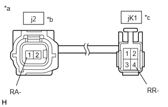
| *a | Front view of Skid Control Sensor Wire RH (No. 1 Parking Brake Wire Assembly) |
| *b | Front view of wire harness connector
(to Sensor Side Connector) |
| *c | Front view of wire harness connector
(to Vehicle Side Connector) |
Measure the resistance according to the value(s) in the table below.
- Standard Resistance:
Tester Connection Condition Specified Condition Click Location & Routing(j2,jK1)Location & Routingewd_type=routing;type=c,w;code=j2,jK1
Click Connector(j2)Body>Parking Brake Wire Assy>Rear Speed Sensor RHewd_type=component;type=c;code=j2;pinno=1
Click Connector(jK1)Body>Parking Brake Wire Assy>Parking Brake Wire Assembly RH and Floor Wireewd_type=component;type=w;code=jK1;pinno=4
j2-1 (RA-) or jK1-4 (RR-) - Body ground and other terminals Always 10 kΩ or higher
- Result:
Proceed to OK NG
Post-procedure1
None
OK
NG
Procedure1
Make sure that there is no looseness at the locking part and the connecting part of the connectors.
- OK:
The connector is securely connected.
Pre-procedure1
Disconnect the A40 skid control ECU (brake actuator assembly) connector.
Disconnect the jK1 skid control sensor wire RH (No. 1 parking brake wire assembly) connector.
Procedure2
Check both the connector case and the terminals for deformation and corrosion.
- OK:
No deformation or corrosion.
Procedure3
Measure the resistance according to the value(s) in the table below.
- Standard Resistance:
Tester Connection Condition Specified Condition Click Location & Routing(jK1,A40)Location & Routingewd_type=routing;type=w,c;code=jK1,A40
Click Connector(jK1)Body>Parking Brake Wire Assy>Parking Brake Wire Assembly RH and Floor Wireewd_type=component;type=w;code=jK1;pinno=4
Click Connector(A40)Engine Compartment>Engine Room Main Wire / Transmission Wire>Brake Actuator Assemblyewd_type=component;type=c;code=A40;pinno=37
jK1-4 (RR-) or A40-37 (RR-) - Body ground Always 10 kΩ or higher
- HINT:
-
The rear speed sensor RH (for 2WD) and rear speed sensor rotor RH are incorporated into the rear axle hub and bearing assembly RH.
-
If the rear speed sensor RH (for 2WD) and rear speed sensor rotor RH need to be replaced, replace the rear axle hub and bearing assembly RH.
- Result:
Proceed to OK NG
Post-procedure1
None
OK
for 2WD: Click hereDrivetrain>AXLE AND DIFFERENTIAL>REAR AXLE HUB (for 2WD)>REMOVAL202203,202303,_52,_111808,_0501217,RM1000000022EDC,202303,999999,_52,_111808,_0501217,RM100000002B3B5,
NG
Procedure1
Make sure that there is no looseness at the locking part and the connecting part of the connectors.
- OK:
The connector is securely connected.
Pre-procedure1
Disconnect the jK1 skid control sensor wire RH (No. 1 parking brake wire assembly) connector.
Procedure2
Check both the connector case and the terminals for deformation and corrosion.
- OK:
No deformation or corrosion.
Procedure3
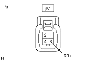
| *a | Front view of wire harness connector
(to Skid Control Sensor Wire RH (No. 1 Parking Brake Wire Assembly)) |
Measure the voltage according to the value(s) in the table below.
- Standard Voltage:
Tester Connection Condition Specified Condition Click Location & Routing(jK1)Location & Routingewd_type=routing;type=w;code=jK1
Click Connector(jK1)Body>Parking Brake Wire Assy>Parking Brake Wire Assembly RH and Floor Wireewd_type=component;type=w;code=jK1;pinno=3
jK1-3 (RR+) - Body ground Ignition switch off Below 1.5 V
- Result:
Proceed to OK NG
Post-procedure1
None
OK
NG
Procedure1
Make sure that there is no looseness at the locking part and the connecting part of the connectors.
- OK:
The connector is securely connected.
Pre-procedure1
Disconnect the A40 skid control ECU (brake actuator assembly) connector.
Disconnect the jK1 skid control sensor wire RH (No. 1 parking brake wire assembly) connector.
Procedure2
Check both the connector case and the terminals for deformation and corrosion.
- OK:
No deformation or corrosion.
Procedure3
| *a | Front view of wire harness connector
(to Skid Control Sensor Wire RH (No. 1 Parking Brake Wire Assembly)) |
Measure the voltage according to the value(s) in the table below.
- Standard Voltage:
Tester Connection Condition Specified Condition Click Location & Routing(jK1)Location & Routingewd_type=routing;type=w;code=jK1
Click Connector(jK1)Body>Parking Brake Wire Assy>Parking Brake Wire Assembly RH and Floor Wireewd_type=component;type=w;code=jK1;pinno=3
jK1-3 (RR+) - Body ground Always Below 1.5 V
- Result:
Proceed to OK NG
Post-procedure1
None
OK
NG
Procedure1
Make sure that there is no looseness at the locking part and the connecting part of the connectors.
- OK:
The connector is securely connected.
Pre-procedure1
Disconnect the jK1 skid control sensor wire RH (No. 1 parking brake wire assembly) connector.
Procedure2
Check both the connector case and the terminals for deformation and corrosion.
- OK:
No deformation or corrosion.
Pre-procedure2
Turn the ignition switch to ON.
Procedure3
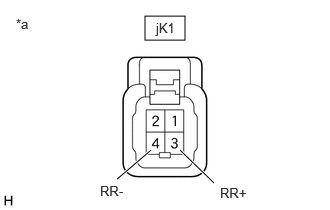
| *a | Front view of wire harness connector
(to Skid Control Sensor Wire RH (No. 1 Parking Brake Wire Assembly)) |
Measure the voltage according to the value(s) in the table below.
- Standard Voltage:
Tester Connection Condition Specified Condition Click Location & Routing(jK1)Location & Routingewd_type=routing;type=w;code=jK1
Click Connector(jK1)Body>Parking Brake Wire Assy>Parking Brake Wire Assembly RH and Floor Wireewd_type=component;type=w;code=jK1;pinno=3,4
jK1-3 (RR+) - jK1-4 (RR-) Ignition switch ON 11 to 14 V
- Result:
Proceed to OK NG
Post-procedure1
None
OK
NG
Procedure1
Make sure that there is no looseness at the locking part and the connecting part of the connectors.
- OK:
The connector is securely connected.
Pre-procedure1
Disconnect the jK1 skid control sensor wire RH (No. 1 parking brake wire assembly) connector.
Procedure2
Check both the connector case and the terminals for deformation and corrosion.
- OK:
No deformation or corrosion.
Pre-procedure2
Turn the ignition switch to ON.
Procedure3
| *a | Front view of wire harness connector
(to Skid Control Sensor Wire RH (No. 1 Parking Brake Wire Assembly)) |
Measure the voltage according to the value(s) in the table below.
- Standard Voltage:
Tester Connection Condition Specified Condition Click Location & Routing(jK1)Location & Routingewd_type=routing;type=w;code=jK1
Click Connector(jK1)Body>Parking Brake Wire Assy>Parking Brake Wire Assembly RH and Floor Wireewd_type=component;type=w;code=jK1;pinno=3
jK1-3 (RR+) - Body ground Ignition switch ON 11 to 14 V
- Result:
Proceed to OK NG
Post-procedure1
None
OK
NG
Procedure1
Make sure that there is no looseness at the locking part and the connecting part of the connectors.
- OK:
The connector is securely connected.
Pre-procedure1
Disconnect the A40 skid control ECU (brake actuator assembly) connector.
Disconnect the jK1 skid control sensor wire RH (No. 1 parking brake wire assembly) connector.
Procedure2
Check both the connector case and the terminals for deformation and corrosion.
- OK:
No deformation or corrosion.
Procedure3
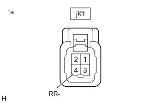
| *a | Front view of wire harness connector
(to Skid Control Sensor Wire RH (No. 1 Parking Brake Wire Assembly)) |
Measure the voltage according to the value(s) in the table below.
- Standard Voltage:
Tester Connection Condition Specified Condition Click Location & Routing(jK1)Location & Routingewd_type=routing;type=w;code=jK1
Click Connector(jK1)Body>Parking Brake Wire Assy>Parking Brake Wire Assembly RH and Floor Wireewd_type=component;type=w;code=jK1;pinno=4
jK1-4 (RR-) - Body ground Always Below 1.5 V
- Result:
Proceed to OK NG
Post-procedure1
None
OK
NG
Procedure1
Make sure that there is no looseness at the locking part and the connecting part of the connectors.
- OK:
The connector is securely connected.
Pre-procedure1
Disconnect the A40 skid control ECU (brake actuator assembly) connector.
Disconnect the jK1 skid control sensor wire RH (No. 1 parking brake wire assembly) connector.
Procedure2
Check both the connector case and the terminals for deformation and corrosion.
- OK:
No deformation or corrosion.
Procedure3
Measure the resistance according to the value(s) in the table below.
- Standard Resistance:
Tester Connection Condition Specified Condition Click Location & Routing(jK1,A40)Location & Routingewd_type=routing;type=w,c;code=jK1,A40
Click Connector(jK1)Body>Parking Brake Wire Assy>Parking Brake Wire Assembly RH and Floor Wireewd_type=component;type=w;code=jK1;pinno=4,3
Click Connector(A40)Engine Compartment>Engine Room Main Wire / Transmission Wire>Brake Actuator Assemblyewd_type=component;type=c;code=A40;pinno=37,22
jK1-4 (RR-) - A40-37 (RR-) Always Below 1 Ω jK1-3 (RR+) or A40-22 (RR+) - jK1-4 (RR-) or A40-37 (RR-) Always 10 kΩ or higher
- Result:
Proceed to OK NG
Post-procedure1
None
OK
NG
Procedure1
Make sure that there is no looseness at the locking part and the connecting part of the connectors.
- OK:
The connector is securely connected.
Pre-procedure1
Disconnect the A40 skid control ECU (brake actuator assembly) connector.
Disconnect the jK1 skid control sensor wire RH (No. 1 parking brake wire assembly) connector.
Procedure2
Check both the connector case and the terminals for deformation and corrosion.
- OK:
No deformation or corrosion.
Procedure3
Measure the resistance according to the value(s) in the table below.
- Standard Resistance:
Tester Connection Condition Specified Condition Click Location & Routing(jK1,A40)Location & Routingewd_type=routing;type=w,c;code=jK1,A40
Click Connector(jK1)Body>Parking Brake Wire Assy>Parking Brake Wire Assembly RH and Floor Wireewd_type=component;type=w;code=jK1;pinno=3
Click Connector(A40)Engine Compartment>Engine Room Main Wire / Transmission Wire>Brake Actuator Assemblyewd_type=component;type=c;code=A40;pinno=22
jK1-3 (RR+) - A40-22 (RR+) Always Below 1 Ω jK1-3 (RR+) or A40-22 (RR+) - Body ground Always 10 kΩ or higher
- Result:
Proceed to OK NG
Post-procedure1
None
OK
NG