BRAKE CONTROL / DYNAMIC CONTROL SYSTEMS REAR SPEED SENSOR(for AWD) REMOVAL
CAUTION / NOTICE / HINT
The necessary procedures (adjustment, calibration, initialization, or registration) that must be performed after parts are removed and installed, or replaced during rear skid control sensor removal/installation are shown below.
| Replaced Part or Performed Procedure | Necessary Procedure | Effect/Inoperative Function when Necessary Procedure not Performed | Link |
|---|---|---|---|
|
*1: Also necessary after performing a tire rotation. *2: It is not necessary to perform this procedure if the tire pressure warning valve and transmitters are installed to the same location. |
|||
| Tires | ·
Initialization*1*2 ·
Tire Position Identification*1*2 |
Tire Pressure Warning System | Refer to Procedures Necessary When Replacing Parts (for Tire Pressure Warning System)
(  202303,202406,_V1,_111780,_0504977,RM100000002AA1Y,202406,202409,_V1,_111780,_0504977,RM100000002MO96,202409,999999,_V1,_111780,_0504977,RM100000002OMBP,) 202303,202406,_V1,_111780,_0504977,RM100000002AA1Y,202406,202409,_V1,_111780,_0504977,RM100000002MO96,202409,999999,_V1,_111780,_0504977,RM100000002OMBP,)
|
- NOTICE:
- ·
After the ignition switch is turned off, the radio and display receiver assembly records various types of memory and settings. As a result, after turning the ignition switch off, make sure to wait at least 1 minutes before disconnecting the cable from the negative (-) auxiliary battery terminal.
·When the cable is disconnected from the negative (-) auxiliary battery terminal and the security lock setting has been enabled, multi-display operations will be disabled upon next startup unless the password is entered. Be sure to check the security lock setting before disconnecting the cable from the negative (-) auxiliary battery terminal.
- HINT:
- ·
Use the same procedure for the RH side and LH side.
·The following procedure is for the LH side.
PROCEDURE

 1.REMOVE REAR WHEEL
89544E
2.REMOVE REAR SKID CONTROL SENSOR
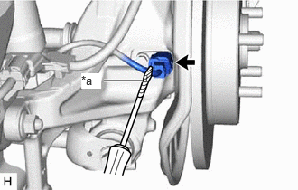
| *a | Protective Tape |
Using a screwdriver with its tip wrapped with protective tape, disconnect the parking brake wire assembly connector from the rear skid control sensor.
- NOTICE:
- ·
Remove any dirt or foreign matter on and around the parking brake wire assembly connector before performing this step.
·Do not allow water, oil or dirt to enter the parking brake wire assembly connector.
·Be careful not to damage the rear skid control sensor or connector cover.
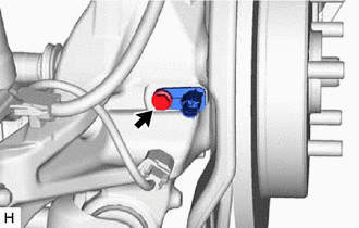
Remove the bolt and the rear skid control sensor from the rear axle carrier sub-assembly.
- NOTICE:
- ·
Keep the tip of the rear skid control sensor and installation hole free of foreign matter.
·Do not rotate or apply excessive force to the rear skid control sensor when removing it from the rear axle carrier sub-assembly. Rotating or applying excessive force may result in damage to the rear skid control sensor.