RM38N0EC
_59
Vehicle Exterior
_111837
MIRROR (EXT)
_0510739
POWER MIRROR CONTROL SYSTEM(w/o Memory)
U
MIRROR (EXT) POWER MIRROR CONTROL SYSTEM(w/o Memory) TERMINALS OF ECU
CHECK MAIN BODY ECU (MULTIPLEX NETWORK BODY ECU) AND POWER DISTRIBUTION BOX ASSEMBLY
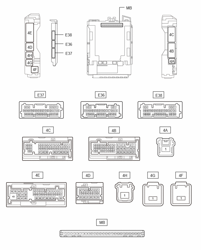
3.396,3.25 3.781,3.479
0.385,0.229
1.521,4.5 1.906,4.729
0.385,0.229
3.875,4.5 4.26,4.729
0.385,0.229
5.698,4.5 6.083,4.729
0.385,0.229
1.146,6.104 1.531,6.333
0.385,0.229
2.938,6.104 3.323,6.333
0.385,0.229
4.25,6.104 4.635,6.333
0.385,0.229
3.438,7.781 3.823,8.01
0.385,0.229
1.24,3.24 1.625,3.469
0.385,0.229
5.26,6.104 5.646,6.333
0.385,0.229
6.26,6.104 6.646,6.333
0.385,0.229
5.458,3.25 5.844,3.479
0.385,0.229
1.958,1.229 2.26,1.229
false
4.26,0.813 4.26,0.26
4.26,0.26 4.438,0.26
false
1.958,1.552 2.26,1.552
false
1.958,1.875 2.26,1.875
false
0.969,1.885 1.281,2.083
0.313,0.198
10
false
4H
1.167,2.385 1.479,2.583
0.313,0.198
10
false
4F
0.979,1.083 1.292,1.281
0.313,0.198
10
false
4E
0.979,1.594 1.292,1.792
0.313,0.198
10
false
4D
6.052,2.094 6.365,2.292
0.313,0.198
10
false
4A
2.333,1.49 2.792,1.688
0.458,0.198
10
false
E36
2.333,1.813 2.792,2.01
0.458,0.198
10
false
E37
4.5,0.198 4.885,0.385
0.385,0.188
10
false
MB
1.333,3.292 1.802,3.5
0.469,0.208
10
false
E37
3.49,3.292 3.948,3.49
0.458,0.198
10
false
E36
3.052,6.146 3.51,6.344
0.458,0.198
10
false
4D
5.813,4.542 6.271,4.74
0.458,0.198
10
false
4A
3.542,7.813 4,8.01
0.458,0.198
10
false
MB
6.031,1.729 6.344,1.927
0.313,0.198
10
false
4B
6.031,1.146 6.344,1.344
0.313,0.198
10
false
4C
0.969,2.146 1.281,2.344
0.313,0.198
10
false
4G
3.979,4.552 4.292,4.75
0.313,0.198
10
false
4B
1.635,4.542 1.948,4.74
0.313,0.198
10
false
4C
1.26,6.135 1.573,6.333
0.313,0.198
10
false
4E
4.365,6.146 4.677,6.344
0.313,0.198
10
false
4H
5.354,6.146 5.667,6.344
0.313,0.198
10
false
4G
6.375,6.146 6.688,6.344
0.313,0.198
10
false
4F
5.542,3.302 6,3.5
0.458,0.198
10
false
E38
2.323,1.156 2.781,1.354
0.458,0.198
10
false
E38
a.
Disconnect the power distribution box assembly and main body ECU (multiplex network body ECU) connectors.
b.
Reconnect the power distribution box assembly connectors.
c.
Measure the resistance and voltage according to the value(s) in the table below.
| Terminal No. (Symbol) | Terminal Description | Condition | Specified Condition |
|---|---|---|---|
| MB-13 (GND1) - Body ground | Ground | Always | Below 1 Ω |
| MB-14 (GND2) - Body ground | Ground | Always | Below 1 Ω |
| MB-26 (BECU) - Body ground | Auxiliary battery power supply | Ignition switch off | 11 to 14 V |
| MB-27 (IGR) - Body ground | Ignition power supply (IG signal) | Ignition switch ON | 11 to 14 V |
| Ignition switch off | Below 1 V |
d.
Install the main body ECU (multiplex network body ECU) to power distribution box assembly.
e.
Measure the voltage according to the value(s) in the table below.
| Terminal No. (Symbol) | Terminal Description | Condition | Specified Condition |
|---|---|---|---|
| E36-26 (AMR) - Body ground | Power retract mirror motor drive voltage (Input) | Retractable outer mirror switch on outer mirror switch assembly in auto retract position. | Below 1 V |
| Retractable outer mirror switch on outer mirror switch assembly not in auto retract position. | 11 to 14 V | ||
| E36-27 (RET) - Body ground | Power retract mirror motor drive voltage (Input) | Retractable outer mirror switch on outer mirror switch assembly in retract position. | Below 1 V |
| Retractable outer mirror switch on outer mirror switch assembly not in retract position. | 11 to 14 V | ||
| 4B-2 - Body ground | Mirror heater drive voltage (Output) | ·
Ignition switch ON ·
Rear defogger switch off |
Below 1 V |
·
Ignition switch ON ·
Rear defogger switch on |
11 to 14 V | ||
| 4C-10 - Body ground | Power retract mirror motor drive voltage (Output) | Outer rear view mirror assembly moving to driving position. | 11 to 14 V |
| Outer rear view mirror assembly not moving. | Below 1 V | ||
| 4C-21 - Body ground | Power retract mirror motor drive voltage (Output) | Outer rear view mirror assembly moving to retract position. | 11 to 14 V |
| Outer rear view mirror assembly not moving. | Below 1 V |
CHECK AIR CONDITIONING AMPLIFIER ASSEMBLY
AIR CONDITIONING CONTROL ASSEMBLY