MIRROR (EXT) POWER MIRROR CONTROL SYSTEM(w/ Memory) AUTO Power Retract Mirrors do not operate
DESCRIPTION
The outer mirror switch assembly sends the auto retractable outer mirror switch signal to the main body ECU (multiplex network body ECU). The main body ECU (multiplex network body ECU) sends the auto retract/return signal to the outer mirror control ECU assemblies via CAN communication, which then controls the mirrors.
When the outer mirror control ECU assemblies receive a door lock output signal from the main body ECU (multiplex network body ECU) while the auto retractable outer mirror switch is on, the outer mirror control ECU assemblies operate the retract motors built into the outer rear view mirror assemblies to retract or return the outer rear view mirror assemblies.
WIRING DIAGRAM
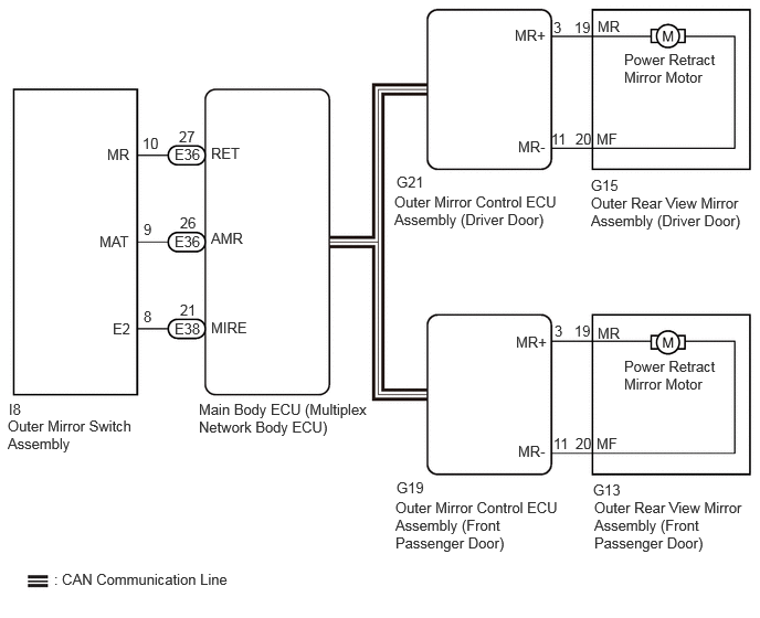
CAUTION / NOTICE / HINT
- NOTICE:
- ·
The power mirror control system (w/ Memory) uses the CAN communication system. Inspect the communication function by following How to Proceed with Troubleshooting. Troubleshoot the power mirror control system (w/ Memory) after confirming that the communication systems are functioning properly.
·Before replacing the main body ECU (multiplex network body ECU), refer to Service Bulletin.
PROCEDURE
Check the power retract mirror function.
- OK:
Power retract mirror function operates normally.
- Result:
Proceed to OK NG
OK
NG
Check the power door lock control system.
- OK:
Power door lock control system is normal.
- Result:
Proceed to OK NG
OK
NG
Check the wireless door lock control system.
- OK:
Wireless door lock control system is normal.
- Result:
Proceed to OK NG
OK
NG
Check the smart entry and start system (for Entry Function).
for Gasoline Model: Click hereVehicle Interior>THEFT DETERRENT / KEYLESS ENTRY>SMART ENTRY AND START SYSTEM (for Entry Function, Gasoline Model)>OPERATION CHECK202111,202203,_58,_111832,_0509383,RM10000000204X9,202203,999999,_58,_111832,_0509383,RM1000000022FON,
- OK:
Smart entry and start system (for Entry Function) is normal.
- Result:
Proceed to OK NG
OK
NG
for Gasoline Model: Click hereVehicle Interior>THEFT DETERRENT / KEYLESS ENTRY>SMART ENTRY AND START SYSTEM (for Entry Function, Gasoline Model)>HOW TO PROCEED WITH TROUBLESHOOTING202111,999999,_58,_111832,_0509383,RM10000000204X8,
for HV Model: Click hereVehicle Interior>THEFT DETERRENT / KEYLESS ENTRY>SMART ENTRY AND START SYSTEM (for Entry Function, HV Model)>HOW TO PROCEED WITH TROUBLESHOOTING202111,999999,_58,_111832,_0509382,RM10000000204WE,
Read the Data List according to the display on the GTS.
- Body Electrical > Main Body > Data List
-
Tester Display Measurement Item Range Normal Condition Diagnostic Note Outer Mirror Auto Switch Retractable outer mirror switch signal OFF or ON OFF: Retractable outer mirror switch not in auto position
ON: Retractable outer mirror switch in auto position-
- Body Electrical > Main Body > Data List
-
Tester Display Outer Mirror Auto Switch - 50003 449 72
- OK:
On the GTS screen, ON or OFF is displayed accordingly.
- Result:
Proceed to OK NG
OK
NG
- Result:
Proceed to OK NG
OK
NG
Disconnect the E36 and E38 main body ECU (multiplex network body ECU).
Measure the resistance according to the value(s) in the table below.
- Standard Resistance:
Tester Connection Condition Specified Condition Click Location & Routing(I8,E36,E38)Location & Routingewd_type=routing;type=c,c,c;code=I8,E36,E38
Click Connector(I8)Body>No. 2 Front Door Wire RH / No. 2 Front Door Wire LH>Outer Mirror Switch Assemblyewd_type=component;type=c;code=I8;pinno=10,9,8
Click Connector(E36)Instrument Panel>Instrument Panel Wire / Radio Wiring Sub-Assy / Telephone Computer Wire>Multiplex Network Body ECUewd_type=component;type=c;code=E36;pinno=27,26
Click Connector(E38)Instrument Panel>Instrument Panel Wire / Radio Wiring Sub-Assy / Telephone Computer Wire>Multiplex Network Body ECUewd_type=component;type=c;code=E38;pinno=21
I8-10 (MR) - E36-27 (RET) Always Below 1 Ω I8-9 (MAT) - E36-26 (AMR) Always Below 1 Ω I8-8 (E2) - E38-21 (MIRE) Always Below 1 Ω I8-10 (MR) or E36-27 (RET) - Body ground Always 10 kΩ or higher I8-9 (MAT) or E36-26 (AMR) - Body ground Always 10 kΩ or higher I8-8 (E2) or E38-21 (MIRE) - Body ground Always 10 kΩ or higher
- Result:
Proceed to OK NG
OK
NG