MIRROR (EXT) OUTER MIRROR SWITCH INSPECTION
PROCEDURE

 84870A
1.INSPECT OUTER MIRROR SWITCH ASSEMBLY (w/o Memory)
84870A
1.INSPECT OUTER MIRROR SWITCH ASSEMBLY (w/o Memory)
Check the mirror select switch and mirror surface adjust switch.
Turn the mirror select switch to the L position.
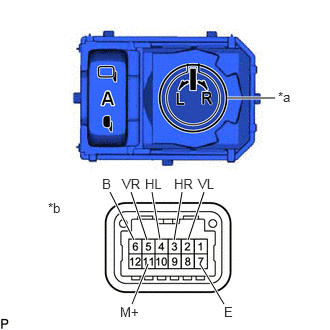
| *a | Mirror Select and Surface Adjust Switch |
| *b | Component without harness connected
(Outer Mirror Switch Assembly) |
Measure the resistance according to the value(s) in the table below.
- Standard Resistance (for left side):
Tester Connection Condition Specified Condition 2 (VL) - 6 (B)
11 (M+) - 7 (E)Up Below 2 Ω Off 10 kΩ or higher 2 (VL) - 7 (E)
11 (M+) - 6 (B)Down Below 2 Ω Off 10 kΩ or higher 4 (HL) - 6 (B)
11 (M+) - 7 (E)Left Below 2 Ω Off 10 kΩ or higher 4 (HL) - 7 (E)
11 (M+) - 6 (B)Right Below 2 Ω Off 10 kΩ or higher
Turn the mirror select switch to the R position.
Measure the resistance according to the value(s) in the table below.
- Standard Resistance (for right side):
Tester Connection Condition Specified Condition 5 (VR) - 6 (B)
11 (M+) - 7 (E)Up Below 2 Ω Off 10 kΩ or higher 5 (VR) - 7 (E)
11 (M+) - 6 (B)Down Below 2 Ω Off 10 kΩ or higher 3 (HR) - 6 (B)
11 (M+) - 7 (E)Left Below 2 Ω Off 10 kΩ or higher 3 (HR) - 7 (E)
11 (M+) - 6 (B)Right Below 2 Ω Off 10 kΩ or higher
If the result is not as specified, replace the outer mirror switch assembly.
Check the mirror retract switch.
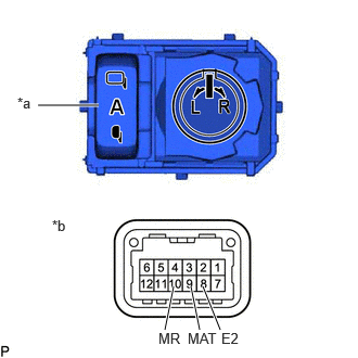
| *a | Retractable Outer Mirror Switch |
| *b | Component without harness connected
(Outer Mirror Switch Assembly) |
Measure the resistance according to the value(s) in the table below.
- Standard Resistance:
Tester Connection Condition Specified Condition 9 (MAT) - 8 (E2) AUTO position Below 35 Ω Except AUTO position 10 kΩ or higher 10 (MR) - 8 (E2) Retract position Below 35 Ω Except retract position 10 kΩ or higher
If the result is not as specified, replace the outer mirror switch assembly.
Check that the LED illuminates.
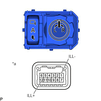
| *a | Component without harness connected
(Outer Mirror Switch Assembly) |
Apply auxiliary battery voltage to the outer mirror switch assembly and check that the LED illuminates.
- OK:
Auxiliary Battery Connection Specified Condition Auxiliary battery positive (+) - 12 (ILL+)
Auxiliary battery negative (-) - 1 (ILL-)LED illuminates
If the result is not as specified, replace the outer mirror switch assembly.
84870A
2.INSPECT OUTER MIRROR SWITCH ASSEMBLY (w/ Memory)
Check the mirror select switch and mirror surface adjust switch.

| *a | Mirror Select and Surface Adjust Switch |
| *b | Component without harness connected
(Outer Mirror Switch Assembly) |
Measure the resistance according to the value(s) in the table below.
- Standard Resistance:
Tester Connection Condition Specified Condition 4 (M+) - 7 (E) Mirror surface adjust switch pushed up 90 to 110 Ω Mirror surface adjust switch pushed right 225 to 275 Ω Mirror surface adjust switch pushed down 437 to 503 Ω Mirror surface adjust switch pushed left 744 to 856 Ω Mirror surface adjust switch not pushed 10 kΩ or higher 5 (MSW) - 7 (E) Mirror select switch turned to R position Below 10 Ω Mirror select switch turned to L position 90 to 110 Ω Mirror select switch off 10 kΩ or higher
If the result is not as specified, replace the outer mirror switch assembly.
Check the mirror retract switch.
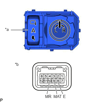
| *a | Retractable Outer Mirror Switch |
| *b | Component without harness connected
(Outer Mirror Switch Assembly) |
Measure the resistance according to the value(s) in the table below.
- Standard Resistance:
Tester Connection Condition Specified Condition 9 (MAT) - 8 (E) AUTO position Below 35 Ω Except AUTO position 10 kΩ or higher 10 (MR) - 8 (E) Retract position Below 35 Ω Except retract position 10 kΩ or higher
If the result is not as specified, replace the outer mirror switch assembly.
Check that the LED illuminates.
| *a | Component without harness connected
(Outer Mirror Switch Assembly) |
Apply auxiliary battery voltage to the outer mirror switch assembly and check that the LED illuminates.
- OK:
Auxiliary Battery Connection Specified Condition Auxiliary battery positive (+) - 12 (ILL+)
Auxiliary battery negative (-) - 1 (ILL-)LED illuminates
If the result is not as specified, replace the outer mirror switch assembly.