WIPER / WASHER WIPER AND WASHER SYSTEM B127987 Humidity/Rain Sensor Missing Message
DESCRIPTION
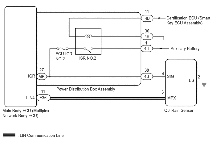
The main body ECU (multiplex network body ECU) and rain sensor communicate via LIN communication. The main body ECU (multiplex network body ECU) stores this DTC if communication becomes abnormal.
| DTC No. | Detection Item | DTC Detection Condition | Trouble Area | Memory | DTC Output from |
|---|---|---|---|---|---|
| B127987 | Humidity/Rain Sensor Missing Message | Detection Condition:
Auxiliary battery voltage is 9.5 V or more Malfunction Status:
Communication malfunction with rain sensor Malfunction Duration:
10 seconds or more |
·
Rain sensor ·
Harness or connector ·
Main body ECU (multiplex network body ECU) ·
Power distribution box assembly |
○ | Main Body |
WIRING DIAGRAM
CAUTION / NOTICE / HINT
- NOTICE:
- ·
Inspect the fuses of circuits related to this system before performing the following procedure.
·Before replacing the main body ECU (multiplex network body ECU), refer to Service Bulletin.
PROCEDURE
Read the DTCs.
- Body Electrical > Main Body > Trouble Codes
- 50001 449
- Result:
Result Proceed to Only DTC B127987 is output A DTC B127987 and B276C88 are output B
A
B
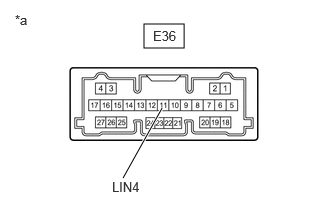
Disconnect the E36 main body ECU (multiplex network body ECU) connector.
Disconnect the Q3 rain sensor connector.
Measure the resistance according to the value(s) in the table below.
- Standard Resistance:
Tester Connection Condition Specified Condition Click Location & Routing(E36,Q3)Location & Routingewd_type=routing;type=c,c;code=E36,Q3
Click Connector(E36)Instrument Panel>Instrument Panel Wire / Radio Wiring Sub-Assy / Telephone Computer Wire>Multiplex Network Body ECUewd_type=component;type=c;code=E36;pinno=11
Click Connector(Q3)Body>Roof Wire>Rain Sensorewd_type=component;type=c;code=Q3;pinno=3
E36-11 (LIN4) - Q3-3 (MPX) Always Below 1 Ω E36-11 (LIN4) or Q3-3 (MPX) - Body ground Always 10 kΩ or higher
- Result:
Proceed to OK NG
OK
NG
| *a | Component without harness connected
(Main Body ECU (Multiplex Network Body ECU) |
Check for pulses according to the value(s) in the table below.
- Standard Pulse:
Tester Connection Condition Specified Condition Click Location & Routing(E36)Location & Routingewd_type=routing;type=c;code=E36
Click Connector(E36)Instrument Panel>Instrument Panel Wire / Radio Wiring Sub-Assy / Telephone Computer Wire>Multiplex Network Body ECUewd_type=component;type=c;code=E36;pinno=11
E36-11 (LIN4) - Body ground Ignition switch ON Pulse generation
- Result:
Proceed to OK NG
OK
NG
Measure the voltage according to the value(s) in the table below.
- Standard Voltage:
Tester Connection Condition Specified Condition Click Location & Routing(Q3)Location & Routingewd_type=routing;type=c;code=Q3
Click Connector(Q3)Body>Roof Wire>Rain Sensorewd_type=component;type=c;code=Q3;pinno=4
Q3-4 (SIG) - Body ground Ignition switch ON 11 to 14 V
- Result:
Proceed to OK NG
OK
NG
Measure the resistance according to the value(s) in the table below.
- Standard Resistance:
Tester Connection Condition Specified Condition Click Location & Routing(Q3)Location & Routingewd_type=routing;type=c;code=Q3
Click Connector(Q3)Body>Roof Wire>Rain Sensorewd_type=component;type=c;code=Q3;pinno=2
Q3-2 (ES) - Body ground Always Below 1 Ω
- Result:
Proceed to OK NG
OK
NG
Disconnect the 4B power distribution box assembly connector.
Measure the resistance according to the value(s) in the table below.
- Standard Resistance:
Tester Connection Condition Specified Condition Click Location & Routing(Q3)Location & Routingewd_type=routing;type=c;code=Q3
Click Connector(Q3)Body>Roof Wire>Rain Sensorewd_type=component;type=c;code=Q3;pinno=4
4B-38 - Q3-4 (SIG) Always Below 1 Ω
- Result:
Proceed to OK NG
OK
NG