BRAKE CONTROL / DYNAMIC CONTROL SYSTEMS ELECTRONICALLY CONTROLLED BRAKE SYSTEM(for Gasoline Model) C050612 Right Front Wheel Speed Sensor Circuit Short to Battery
DESCRIPTION
Each speed sensor detects wheel speed and sends signals to the skid control ECU (brake actuator assembly). These signals are used by the ABS control.
The speed sensor detects the magnetic fields of the speed sensor rotor as it rotates and outputs a pulse signal.
The frequency of the pulse varies in accordance with the rotational speed of the speed sensor rotor and the system uses this to determine the wheel speed.
| DTC No. | Detection Item | DTC Detection Condition | Trouble Area | DTC Output from | Priority |
|---|---|---|---|---|---|
| C050612 | Right Front Wheel Speed Sensor Circuit Short to Battery | A short to +B in the speed sensor signal circuit is detected for 0.12 seconds or more. | ·
Front speed sensor RH ·
Wire harness or connector ·
Skid control ECU (brake actuator assembly) |
Brake/EPB | A |
WIRING DIAGRAM
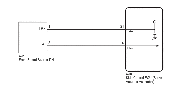
PROCEDURE
Procedure1
Make sure that there is no looseness at the locking part and the connecting part of the connectors.
- OK:
The connector is securely connected.
Pre-procedure1
Disconnect the A41 front speed sensor RH connector.
Procedure2
Check both the connector case and the terminals for deformation and corrosion.
- OK:
No deformation or corrosion.
Pre-procedure2
Turn the ignition switch to ON.
Procedure3
Measure the voltage according to the value(s) in the table below.
- Standard Voltage:
Tester Connection Condition Specified Condition Click Location & Routing(A41)Location & Routingewd_type=routing;type=c;code=A41
Click Connector(A41)Engine Compartment>Engine Room Main Wire / Transmission Wire>Front Speed Sensor RHewd_type=component;type=c;code=A41;pinno=1,2
A41-1 (FR+) - A41-2 (FR-) Ignition switch ON 11 to 14 V
- Result:
Proceed to OK NG
Post-procedure1
None
OK
NG
Procedure1
Make sure that there is no looseness at the locking part and the connecting part of the connectors.
- OK:
The connector is securely connected.
Pre-procedure1
Disconnect the A40 skid control ECU (brake actuator assembly) connector.
Disconnect the A41 front speed sensor RH connector.
Procedure2
Check both the connector case and the terminals for deformation and corrosion.
- OK:
No deformation or corrosion.
Procedure3
Measure the voltage according to the value(s) in the table below.
- Standard Voltage:
Tester Connection Condition Specified Condition Click Location & Routing(A41)Location & Routingewd_type=routing;type=c;code=A41
Click Connector(A41)Engine Compartment>Engine Room Main Wire / Transmission Wire>Front Speed Sensor RHewd_type=component;type=c;code=A41;pinno=2
A41-2 (FR-) - Body ground Always Below 1.5 V
- Result:
Proceed to OK NG
Post-procedure1
None
OK
NG
Procedure1
Make sure that there is no looseness at the locking part and the connecting part of the connectors.
- OK:
The connector is securely connected.
Pre-procedure1
Disconnect the A40 skid control ECU (brake actuator assembly) connector.
Disconnect the A41 front speed sensor RH connector.
Procedure2
Check both the connector case and the terminals for deformation and corrosion.
- OK:
No deformation or corrosion.
Procedure3
Measure the resistance according to the value(s) in the table below.
- Standard Resistance:
Tester Connection Condition Specified Condition Click Location & Routing(A41,A40)Location & Routingewd_type=routing;type=c,c;code=A41,A40
Click Connector(A41)Engine Compartment>Engine Room Main Wire / Transmission Wire>Front Speed Sensor RHewd_type=component;type=c;code=A41;pinno=1,2
Click Connector(A40)Engine Compartment>Engine Room Main Wire / Transmission Wire>Brake Actuator Assemblyewd_type=component;type=c;code=A40;pinno=21,26
A41-1 (FR+) or A40-21 (FR+) - A41-2 (FR-) or A40-26 (FR-) Always 10 kΩ or higher
- Result:
Proceed to OK NG
Post-procedure1
None
OK
NG