BRAKE CONTROL / DYNAMIC CONTROL SYSTEMS FRONT SPEED SENSOR REMOVAL
CAUTION / NOTICE / HINT
The necessary procedures (adjustment, calibration, initialization, or registration) that must be performed after parts are removed and installed, or replaced during front speed sensor removal/installation are shown below.
| Replaced Part or Performed Procedure | Necessary Procedure | Effect/Inoperative Function when Necessary Procedure not Performed | Link |
|---|---|---|---|
|
*1: Also necessary after performing a tire rotation. *2: It is not necessary to perform this procedure if the tire pressure warning valve and transmitters are installed to the same location. |
|||
| Tires | ·
Initialization*1*2 ·
Tire Position Identification*1*2 |
Tire Pressure Warning System | Refer to Procedures Necessary When Replacing Parts (for Tire Pressure Warning System)
(  202203,202303,_V1,_111780,_0504977,RM1000000022CKZ,202303,202406,_V1,_111780,_0504977,RM100000002AA1Y,202406,999999,_V1,_111780,_0504977,RM100000002MO96,) 202203,202303,_V1,_111780,_0504977,RM1000000022CKZ,202303,202406,_V1,_111780,_0504977,RM100000002AA1Y,202406,999999,_V1,_111780,_0504977,RM100000002MO96,)
|
CAUTION / NOTICE / HINT
- HINT:
- ·
Use the same procedure for the RH side and LH side.
·The following procedure is for the LH side.
PROCEDURE

 1.REMOVE FRONT WHEEL
53896B
2.REMOVE FRONT FENDER FRONT SPLASH SHIELD
for M20C-FKS, M20D-FKS: Click hereEngine / Hybrid System>M20C-FKS, M20D-FKS (ENGINE MECHANICAL)>ENGINE ASSEMBLY>REMOVAL202203,202303,_51,_111786,_0499722,RM1000000022F78_01_0304,202303,202406,_51,_111786,_0499722,RM100000002A0JY_01_0304,202406,999999,_51,_111786,_0499722,RM100000002MXOE_01_0304,
for A25D-FXS, A25F-FXS: Click hereEngine / Hybrid System>A25D-FXS, A25F-FXS (ENGINE MECHANICAL)>ENGINE ASSEMBLY>REMOVAL202203,202303,_51,_111795,_0503439,RM1000000022F56_01_0304,202303,202406,_51,_111795,_0503439,RM100000002AMBS_01_0304,202406,999999,_51,_111795,_0503439,RM100000002MPYT_01_0304,
53876A
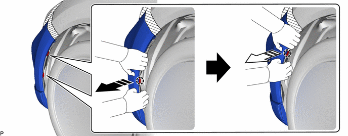
3.SEPARATE FRONT FENDER LINER
As shown in the illustration, pull the front bumper assembly horizontally to release each claw and disengage the front fender liner retainer.

|
Remove in this Direction (1) | 
|
Remove in this Direction (2) |
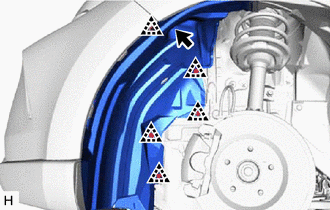
Remove the screw and 5 clips.
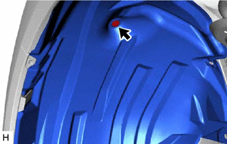
Remove the grommet.
89543
4.REMOVE FRONT SPEED SENSOR
Turn back the front fender liner.
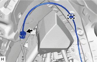
Disconnect the front speed sensor connector.
Disengage the clamp.
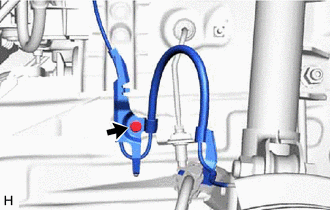
Remove the bolt and separate the sensor clamp.
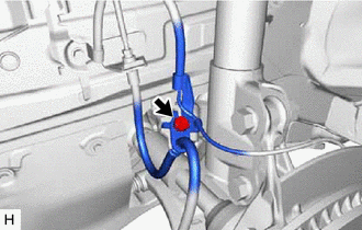
Remove the bolt and separate the front flexible hose and sensor clamp.
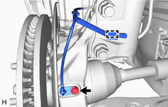
Disengage the clamp to separate the sensor clamp.
Remove the bolt and front speed sensor from the steering knuckle.
- NOTICE:
- ·
Keep the tip of the front speed sensor and installation hole free of foreign matter.
·Do not rotate or apply excessive force to the front speed sensor when removing it from the steering knuckle. Rotating or applying excessive force may result in damage to the front speed sensor.