TELEMATICS TELEMATICS SYSTEM B15C464 Airbag Signal Signal Plausibility Failure
DESCRIPTION
If the telematics transceiver detects an error in communication between the telematics transceiver and the airbag sensor assembly as a result of the telematics transceiver self check, this DTC will be set.
| DTC No. | Detection Item | DTC Detection Condition | Trouble Area |
|---|---|---|---|
| B15C464 | Airbag Signal Signal Plausibility Failure | Telematics transceiver detects an error in signals from airbag sensor assembly when ignition switch to ON. | ·
Airbag system ·
Harness or connector ·
Airbag sensor assembly ·
Telematics transceiver |
WIRING DIAGRAM
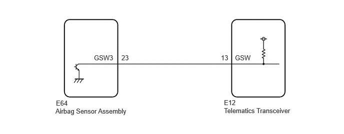
CAUTION / NOTICE / HINT
- NOTICE:
- ·
Depending on the parts that are replaced during vehicle inspection or maintenance, performing initialization, registration or calibration may be needed. Refer to Precaution for Telematics System.
·The vehicle is equipped with an SRS (Supplemental Restraint System) which includes components such as airbags. Before servicing (including removal or installation of parts), be sure to read the Precaution in the SRS.
·When replacing the telematics transceiver, make sure to replace it with a new one.
·Before replacing the telematics transceiver, refer to Service Bulletin.
·After turning the ignition switch off, waiting time may be required before disconnecting the cable from the negative (-) auxiliary battery terminal.
PROCEDURE
Turn the ignition switch off.
Connect the GTS to the DLC3.
Turn the ignition switch to ON and wait for 10 seconds.
Turn the GTS on.
Check the DTC of "AIRBAG SYSTEM".
- Result:
Result Proceed to DTCs are not output A DTCs are output B
A
B
Turn the ignition switch off.
Connect the GTS to the DLC3.
Turn the ignition switch to ON and wait for 10 seconds or more.
Turn the GTS on.
Check for DTCs and check that no DTCs are output.
- Body Electrical > Telematics > Trouble Codes
- 50001 459
- OK:
No DTCs are output.
- Result:
Proceed to OK NG
OK
NG
| *a | Component with harness connected
(Telematics Transceiver) |
Remove the telematics transceiver but do not disconnect the connectors.
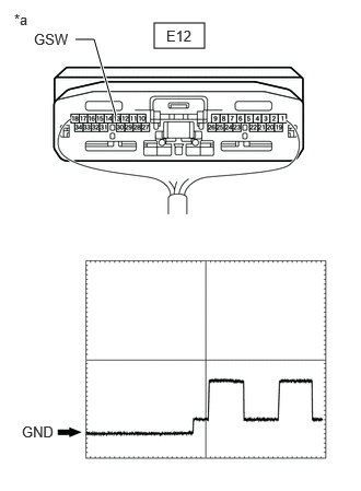
Check the input waveform.
Check the signal waveform according to the condition(s) in the table below. (Check the waveform from the back of the wire harness connector of the telematics transceiver while the airbag sensor assembly connectors are connected.)
- Reference Waveform:
Item Condition Tester connection E12-13 (GSW) - Body ground Tool setting 5.0 V/DIV., 20 ms./DIV. Vehicle condition Ignition switch to ON
- OK:
The waveform is similar to that shown in the illustration.
- Result:
Proceed to OK NG
OK
NG
Replace the telematics transceiver with a new one.
- Result:
Proceed to NEXT
NEXT
Disconnect the E12 telematics transceiver connector.
Disconnect the E64 airbag sensor assembly connector.
Measure the resistance according to the value(s) in the table below.
- Standard Resistance:
Tester Connection Condition Specified Condition Click Location & Routing(E12,E64)Location & Routingewd_type=routing;type=c,c;code=E12,E64
Click Connector(E12)Instrument Panel>Instrument Panel Wire / Telephone Computer Wire>Telephone Transceiverewd_type=component;type=c;code=E12;pinno=13
Click Connector(E64)Instrument Panel>Instrument Panel Wire / Telephone Computer Wire>Airbag Sensor Assemblyewd_type=component;type=c;code=E64;pinno=23
E12-13 (GSW) - E64-23 (GSW3) Always Below 1 Ω E12-13 (GSW) - Body ground Always 10 kΩ or higher
- Result:
Proceed to OK NG
OK
NG