PARK ASSIST / MONITORING TOYOTA PARKING ASSIST-SENSOR SYSTEM No. 1 Clearance Warning Buzzer Circuit
DESCRIPTION
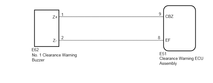
This circuit consists of the No. 1 clearance warning buzzer and clearance warning ECU assembly. An ECU-excited type buzzer is used. The ECU operates the buzzers using a sound pattern that changes depending on the distance to the obstacle.
WIRING DIAGRAM
CAUTION / NOTICE / HINT
- NOTICE:
-
Perform registration after replacing or removing and installing the ultrasonic sensor or clearance warning ECU assembly.
PROCEDURE
Connect the GTS to the DLC3.
Turn the ignition switch to ON.
Turn the GTS on.
Enter the following menus: Body Electrical / Clearance Warning / Active Test.
Check that the buzzer operates by performing the Active Test.
- Body Electrical > Clearance Warning > Active Test
-
Tester Display Measurement Item Control Range Diagnostic Note Front Buzzer No. 1 clearance warning buzzer OFF or ON Confirm that the vehicle is stopped and the ignition switch is ON
- Body Electrical > Clearance Warning > Active Test
-
Tester Display Front Buzzer - 50004 438 1
- OK:
The No. 1 clearance warning buzzer sounds.
- Result:
Proceed to OK NG
OK
NG
Disconnect the E51 clearance warning ECU assembly connector.
Disconnect the E62 No. 1 clearance warning buzzer connector.
Measure the resistance according to the value(s) in the table below.
- Standard Resistance:
Tester Connection Condition Specified Condition Click Location & Routing(E51,E62)Location & Routingewd_type=routing;type=c,c;code=E51,E62
Click Connector(E51)Instrument Panel>Instrument Panel Wire / Radio Wiring Sub-Assy / Telephone Computer Wire>Clearance Warning ECU Assemblyewd_type=component;type=c;code=E51;pinno=9,8
Click Connector(E62)Instrument Panel>Instrument Panel Wire / Radio Wiring Sub-Assy / Telephone Computer Wire>No. 1 Clearance Warning Buzzerewd_type=component;type=c;code=E62;pinno=1,2
E51-9 (CBZ) - E62-1 (Z+) Always Below 1 Ω E51-8 (EF) - E62-2 (Z-) Always Below 1 Ω E51-9 (CBZ) or E62-1 (Z+) - Body ground Always 10 kΩ or higher E51-8 (EF) or E62-2 (Z-) - Body ground Always 10 kΩ or higher
- Result:
Proceed to OK NG
OK
NG
Replace the No. 1 clearance warning buzzer with a new or known good one.
- Result:
Proceed to NEXT
NEXT
Connect the GTS to the DLC3.
Turn the ignition switch to ON.
Turn the GTS on.
Enter the following menus: Body Electrical / Clearance Warning / Active Test.
Check that the buzzer operates by performing the Active Test.
- Body Electrical > Clearance Warning > Active Test
-
Tester Display Measurement Item Control Range Diagnostic Note Front Buzzer No. 1 clearance warning buzzer OFF or ON Confirm that the vehicle is stopped and the ignition switch is ON
- Body Electrical > Clearance Warning > Active Test
-
Tester Display Front Buzzer - 50004 438 1
- OK:
The No. 1 clearance warning buzzer sounds.
- Result:
Proceed to OK NG
OK
NG