PARKING BRAKE ELECTRIC PARKING BRAKE SYSTEM(for Gasoline Model) C060B12 Left Electric Parking Brake Actuator Control Circuit Short to Battery
DESCRIPTION
| DTC No. | Detection Item | DTC Detection Condition | Trouble Area | Memory | DTC Output from | Priority | Note |
|---|---|---|---|---|---|---|---|
| C060B12 | Left Electric Parking Brake Actuator Control Circuit Short to Battery | ·
Diagnosis Condition: Electric parking brake not operating ·
Malfunction Status: The ECU power supply is normal but there is a malfunction in the electric parking brake actuator LH internal circuit (short to +B). ·
Detection Time: Approximately 1 second |
·
Parking brake actuator assembly LH ·
No. 2 parking brake wire assembly ·
Wire harness and connector ·
Skid control ECU (brake actuator assembly) |
DTC stored | Brake/EPB | A | An electric parking brake system malfunction is displayed on the multi-information display. |
WIRING DIAGRAM
PROCEDURE
Pre-procedure1
Turn the ignition switch off.
Make sure the No. 2 parking brake wire assembly is securely installed.
Disconnect the k1 parking brake actuator assembly LH connector.
Procedure1
Measure the voltage according to the value(s) in the table below.
- Standard Voltage:
Tester Connection Condition Specified Condition Click Location & Routing(k1)Location & Routingewd_type=routing;type=c;code=k1
Click Connector(k1)Body>Parking Brake Wire Assy>Parking Brake Actuator Assembly LHewd_type=component;type=c;code=k1;pinno=2,1
k1-2 (LE+) - k1-1 (LE-) Electric parking brake not operating Below 1 V
- Result:
Proceed to OK NG
Post-procedure1
None
OK
NG
Pre-procedure1
Disconnect the kL1 No. 2 parking brake wire assembly connector.
Procedure1
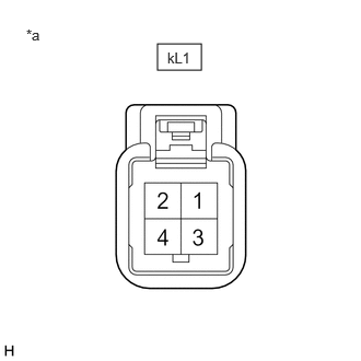
| *a | Front view of wire harness connector
(to No. 2 Parking Brake Wire Assembly) |
Measure the voltage according to the value(s) in the table below.
- Standard Voltage:
Tester Connection Condition Specified Condition Click Location & Routing(kL1)Location & Routingewd_type=routing;type=w;code=kL1
Click Connector(kL1)Body>Parking Brake Wire Assy>Parking Brake Wire Assembly LH and No. 2 Floor Wireewd_type=component;type=w;code=kL1;pinno=1,2
kL1-1 - kL1-2 Electric parking brake not operating Below 1 V
- Result:
Proceed to OK NG
Post-procedure1
None
OK
NG
Pre-procedure1
Disconnect the kL1 No. 2 parking brake wire assembly connector.
Disconnect the A40 skid control ECU (brake actuator assembly) connector.
Procedure1
Measure the voltage according to the value(s) in the table below.
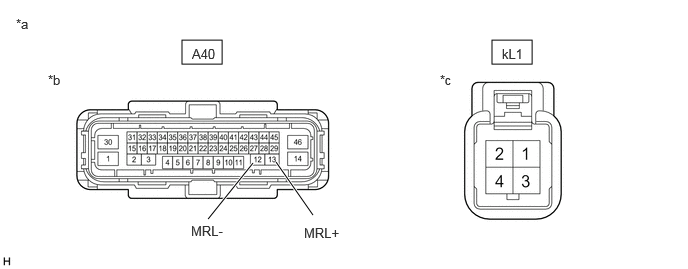
| *a | Front view of wire harness connector | *b | (to Skid Control ECU (Brake Actuator Assembly)) |
| *c | (to No. 2 Parking Brake Wire Assembly) | - | - |
- Standard Voltage:
Tester Connection Condition Specified Condition Click Location & Routing(kL1,A40)Location & Routingewd_type=routing;type=w,c;code=kL1,A40
Click Connector(kL1)Body>Parking Brake Wire Assy>Parking Brake Wire Assembly LH and No. 2 Floor Wireewd_type=component;type=w;code=kL1;pinno=1,2
Click Connector(A40)Engine Compartment>Engine Room Main Wire / Transmission Wire>Brake Actuator Assemblyewd_type=component;type=c;code=A40;pinno=13,12
kL1-1 or A40-13 (MRL+) - Body ground Always Below 1 V kL1-2 or A40-12 (MRL-) - Body ground Always Below 1 V
- Result:
Proceed to OK NG
Post-procedure1
None
OK
NG