PARK ASSIST / MONITORING REAR VIEW MONITOR SYSTEM Image from Camera for Rear View Monitor is Abnormal
DESCRIPTION
The video signal of the rear television camera assembly is transmitted to the radio and display receiver assembly.
WIRING DIAGRAM
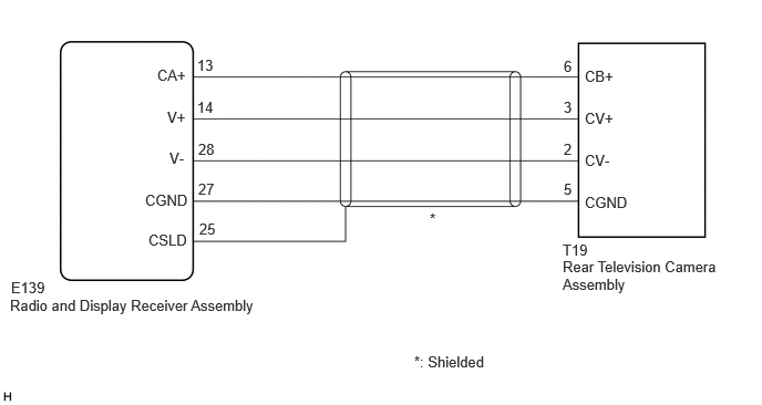
PROCEDURE
Disconnect the E139 radio and display receiver assembly connector.
Disconnect the T19 rear television camera assembly connector.
Measure the resistance according to the value(s) in the table below.
- Standard Resistance:
Tester Connection Condition Specified Condition Click Location & Routing(E139,T19)Location & Routingewd_type=routing;type=c,c;code=E139,T19
Click Connector(E139)Instrument Panel>Instrument Panel Wire / Telephone Computer Wire>Navigation Receiver Assemblyewd_type=component;type=c;code=E139;pinno=13,14,28,27,25
Click Connector(T19)Body>No. 1 Back Door Wire>Rear Television Camera Assemblyewd_type=component;type=c;code=T19;pinno=6,3,2,5
E139-13 (CA+) - T19-6 (CB+) Always Below 1 Ω E139-14 (V+) - T19-3 (CV+) Always Below 1 Ω E139-28 (V-) - T19-2 (CV-) Always Below 1 Ω E139-27 (CGND) - T19-5 (CGND) Always Below 1 Ω E139-25 (CSLD) - Body ground Always Below 1 Ω E139-13 (CA+) or T19-6 (CB+) - Body ground Always 10 kΩ or higher E139-14 (V+) or T19-3 (CV+) - Body ground Always 10 kΩ or higher E139-28 (V-) or T19-2 (CV-) - Body ground Always 10 kΩ or higher E139-27 (CGND) or T19-5 (CGND) - Body ground Always 10 kΩ or higher
- Result:
Proceed to OK NG
OK
NG
Reconnect the E139 radio and display receiver assembly connector.
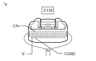
| *a | Component with harness connected
(Radio and Display Receiver Assembly) |
Measure the resistance according to the value(s) in the table below.
- Standard Resistance:
Tester Connection Condition Specified Condition Click Location & Routing(E139)Location & Routingewd_type=routing;type=c;code=E139
Click Connector(E139)Instrument Panel>Instrument Panel Wire / Telephone Computer Wire>Navigation Receiver Assemblyewd_type=component;type=c;code=E139;pinno=28,27
E139-28 (V-) - Body ground Always Below 1 Ω E139-27 (CGND) - Body ground Always Below 1 Ω
Measure the voltage according to the value(s) in the table below.
- Standard Voltage:
Tester Connection Condition Specified Condition Click Location & Routing(E139)Location & Routingewd_type=routing;type=c;code=E139
Click Connector(E139)Instrument Panel>Instrument Panel Wire / Telephone Computer Wire>Navigation Receiver Assemblyewd_type=component;type=c;code=E139;pinno=13,27
E139-13 (CA+) - E139-27 (CGND) Ignition switch ACC 5.5 to 7.05 V
- Result:
Proceed to OK NG
OK
NG
Reconnect the T19 rear television camera assembly connector.
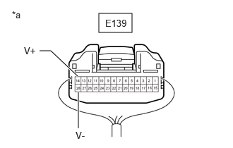
| *a | Component with harness connected
(Radio and Display Receiver Assembly) |
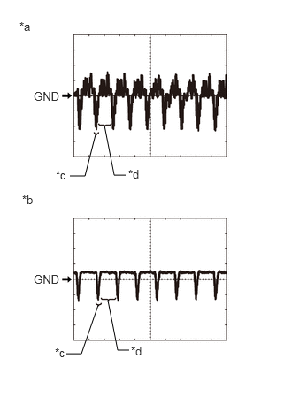
| *a | Waveform 1 (camera lens is not covered, displaying an image) |
| *b | Waveform 2 (camera lens is covered, blacking out the screen) |
| *c | Synchronization Signal |
| *d | Video Waveform |
Using an oscilloscope, check the waveform of the rear television camera assembly.
- HINT:
-
A waterproof connector is used for the rear television camera assembly. Therefore, inspect the waveform at the radio and display receiver assembly with the connector connected.
- OK:
Waveform is similar to that shown in the illustration.
| Item | Content |
|---|---|
| Measurement terminal | E139-14 (V+) - E139-28 (V-) |
| Measurement setting | 200 mV/DIV., 50 μs./DIV. |
| Condition | Ignition switch ON, reverse (R) selected |
- HINT:
- ·
The video waveform changes according to the image sent by the rear television camera assembly.
·The video waveform is constantly output when the ignition switch is turned to ACC.
·Make sure that the rear camera is enabled in general settings.
- Result:
Proceed to OK NG
OK
NG