PARK ASSIST / MONITORING BLIND SPOT MONITOR SYSTEM C1AB412 Outer Mirror Indicator (Module "B" Side) Circuit Short to Battery
DESCRIPTION
This DTC is stored when the blind spot monitor sensor LH (B) detects a short to +B in the outer rear view mirror indicator LH.
| DTC No. | Detection Item | DTC Detection Condition | Trouble Area | DTC Output from | Priority |
|---|---|---|---|---|---|
| C1AB412 | Outer Mirror Indicator (Module "B" Side) Circuit Short to Battery | Both of the following conditions are met:
·
The blind spot monitor system is on ·
The blind spot monitor sensor is not sending voltage to the indicator but the indicator receives voltage above a specified level for a specified period of time |
·
Outer mirror LH (outer rear view mirror indicator LH) ·
Outer rear view mirror assembly LH ·
Harness or connector ·
Blind spot monitor sensor LH (B) |
Blind Spot Monitor "B" | A |
WIRING DIAGRAM
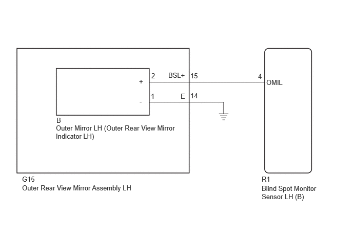
CAUTION / NOTICE / HINT
- NOTICE:
-
When checking for DTCs, make sure that the blind spot monitor system is turned on.
PROCEDURE
Clear the DTCs.
- Body Electrical > Blind Spot Monitor "B" > Clear DTCs
- 50002 460
- Result:
Proceed to NEXT
NEXT
Recheck for DTCs and check if the same DTC is output again.
- Body Electrical > Blind Spot Monitor "B" > Trouble Codes
- 50001 460
- Result:
Result Proceed to DTCs are not output A DTCs are output B
A
B
Pre-procedure1
Disconnect the R1 blind spot monitor sensor LH (B) connector.
Procedure1
Measure the voltage according to the value(s) in the table below.
- Standard Voltage:
Tester Connection Switch Condition Specified Condition Click Location & Routing(R1)Location & Routingewd_type=routing;type=c;code=R1
Click Connector(R1)Body>Luggage Room Wire>Blind Spot Monitor Sensor LHewd_type=component;type=c;code=R1;pinno=4
R1-4 (OMIL) - Body ground Ignition switch ON Below 1 V
- Result:
Proceed to OK NG
Post-procedure1
None
OK
NG
Pre-procedure1
Disconnect the B outer mirror LH (outer rear view mirror indicator LH) connector.
Procedure1
Measure the voltage according to the value(s) in the table below.
- Standard Voltage:
Tester Connection Switch Condition Specified Condition Click Location & Routing(R1)Location & Routingewd_type=routing;type=c;code=R1
Click Connector(R1)Body>Luggage Room Wire>Blind Spot Monitor Sensor LHewd_type=component;type=c;code=R1;pinno=4
R1-4 (OMIL) - Body ground Ignition switch ON Below 1 V
- Result:
Proceed to OK NG
Post-procedure1
None
OK
NG
Pre-procedure1
Disconnect the G15 outer rear view mirror assembly LH connector.
Procedure1
Measure the voltage according to the value(s) in the table below.
- Standard Voltage:
Tester Connection Switch Condition Specified Condition Click Location & Routing(R1)Location & Routingewd_type=routing;type=c;code=R1
Click Connector(R1)Body>Luggage Room Wire>Blind Spot Monitor Sensor LHewd_type=component;type=c;code=R1;pinno=4
R1-4 (OMIL) - Body ground Ignition switch ON Below 1 V
- Result:
Proceed to OK NG
Post-procedure1
None
OK
NG