RM38N0EC
_58
Vehicle Interior
_111833
LIGHTING (INT)
_0499871
LIGHTING SYSTEM
U
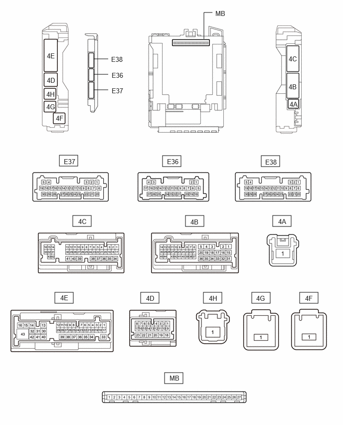
LIGHTING (INT) LIGHTING SYSTEM TERMINALS OF ECU
CHECK MAIN BODY ECU (MULTIPLEX NETWORK BODY ECU) AND POWER DISTRIBUTION BOX ASSEMBLY
3.396,3.25 3.781,3.479
0.385,0.229
1.521,4.5 1.906,4.729
0.385,0.229
3.875,4.5 4.26,4.729
0.385,0.229
5.698,4.5 6.083,4.729
0.385,0.229
1.146,6.104 1.531,6.333
0.385,0.229
2.938,6.104 3.323,6.333
0.385,0.229
4.25,6.104 4.635,6.333
0.385,0.229
3.438,7.781 3.823,8.01
0.385,0.229
1.24,3.24 1.625,3.469
0.385,0.229
5.26,6.104 5.646,6.333
0.385,0.229
6.26,6.104 6.646,6.333
0.385,0.229
5.458,3.25 5.844,3.479
0.385,0.229
1.958,1.229 2.26,1.229
false
4.26,0.813 4.26,0.26
4.26,0.26 4.438,0.26
false
1.958,1.552 2.26,1.552
false
1.958,1.875 2.26,1.875
false
0.969,1.885 1.281,2.083
0.313,0.198
10
false
4H
1.167,2.385 1.479,2.583
0.313,0.198
10
false
4F
0.979,1.083 1.292,1.281
0.313,0.198
10
false
4E
0.979,1.594 1.292,1.792
0.313,0.198
10
false
4D
6.052,2.094 6.365,2.292
0.313,0.198
10
false
4A
2.333,1.49 2.792,1.688
0.458,0.198
10
false
E36
2.333,1.813 2.792,2.01
0.458,0.198
10
false
E37
4.5,0.198 4.885,0.385
0.385,0.188
10
false
MB
1.333,3.292 1.802,3.5
0.469,0.208
10
false
E37
3.49,3.292 3.948,3.49
0.458,0.198
10
false
E36
3.052,6.146 3.51,6.344
0.458,0.198
10
false
4D
5.813,4.542 6.271,4.74
0.458,0.198
10
false
4A
3.542,7.813 4,8.01
0.458,0.198
10
false
MB
6.031,1.729 6.344,1.927
0.313,0.198
10
false
4B
6.031,1.146 6.344,1.344
0.313,0.198
10
false
4C
0.969,2.146 1.281,2.344
0.313,0.198
10
false
4G
3.979,4.552 4.292,4.75
0.313,0.198
10
false
4B
1.635,4.542 1.948,4.74
0.313,0.198
10
false
4C
1.26,6.135 1.573,6.333
0.313,0.198
10
false
4E
4.365,6.146 4.677,6.344
0.313,0.198
10
false
4H
5.354,6.146 5.667,6.344
0.313,0.198
10
false
4G
6.375,6.146 6.688,6.344
0.313,0.198
10
false
4F
5.542,3.302 6,3.5
0.458,0.198
10
false
E38
2.323,1.156 2.781,1.354
0.458,0.198
10
false
E38
a.
Disconnect the power distribution box assembly and main body ECU (multiplex network body ECU) connectors.
b.
Connect the power distribution box assembly connectors.
c.
Measure the voltage and resistance according to the value(s) in the table below.
| Terminal No. (Symbol) | Terminal Description | Condition | Specified Condition |
|---|---|---|---|
| MB-13 (GND1) - Body ground | Ground | Always | Below 1 Ω |
| MB-14 (GND2) - Body ground | Ground | Always | Below 1 Ω |
| MB-26 (BECU) - Body ground | Auxiliary battery power supply | Ignition switch off | 11 to 14 V |
| MB-27 (IGR) - Body ground | IG power supply | Ignition switch off | Below 1 V |
| Ignition switch ON | 11 to 14 V |
d.
Install the main body ECU (multiplex network body ECU).
e.
Connect the power distribution box assembly and main body ECU (multiplex network body ECU) connectors.
f.
Measure the voltage and check for pulses according to the value(s) in the table below.
| Terminal No. (Symbol) | Terminal Description | Condition | Specified Condition |
|---|---|---|---|
|
*: w/ Footwell Light |
|||
| 4F-1 - Body ground | DOME CUT relay drive power supply | Ignition switch off | 11 to 14 V |
| 4E-3 - Body ground | Front door courtesy light switch assembly (for LH) signal | Front door LH open | Below 1 V |
| Front door LH closed | 4.7 to 5.3 V | ||
| 4C-9 - Body ground | Front door courtesy light switch assembly (for RH) signal | Front door RH open | Below 1 V |
| Front door RH closed | 4.7 to 5.3 V | ||
| 4E-26 - Body ground | Rear door courtesy light switch assembly (for LH) signal | Rear door LH open | Below 1 V |
| Rear door LH closed | 4.7 to 5.3 V | ||
| 4E-1 - Body ground | Rear door courtesy light switch assembly (for RH) signal | Rear door RH open | Below 1 V |
| Rear door RH closed | 4.7 to 5.3 V | ||
| 4E-2 - Body ground | Back door lock assembly with courtesy light switch signal | Back door open | Below 1 V |
| Back door closed | 4.7 to 5.3 V | ||
| 4E-18 - Body ground | No. 1 luggage compartment light assembly ground | No. 1 luggage compartment light assembly off | 11 to 14 V |
| No. 1 luggage compartment light assembly on | Below 1 V | ||
| 4E-20 - Body ground | No. 1 luggage compartment light assembly power supply | DOME CUT relay off | 11 to 14 V |
| DOME CUT relay on | Below 1 V | ||
| 4C-4 - Body ground | Interior light power supply | DOME CUT relay off | 11 to 14 V |
| DOME CUT relay on | Below 1 V | ||
| 4C-1 - Body ground | Each instrument panel illumination power supply | Light control switch in neither tail or head position | Below 1 V |
| Light control switch in tail or head position | 11 to 14 V | ||
| 4E-9 - Body ground | Each instrument panel illumination power supply | Light control switch in neither tail or head position | Below 1 V |
| Light control switch in tail or head position | 11 to 14 V | ||
| E37-5 (ILE) - Body ground | Illuminated entry system drive output | Illuminated entry system inactive | 11 to 14 V |
| Illuminated entry system operation | Below 1 V | ||
| 4B-28 - Body ground | Ambient illumination light power supply | Always | 11 to 14 V |
| 4C-18 - Body ground* | Ambient illumination light ground* | Ambient illumination light off | 11 to 14 V |
| Ambient illumination light on | Below 1 V | ||
| 4C-19 - Body ground | Ambient illumination light ground | Ambient illumination light off | 11 to 14 V |
| Ambient illumination light on | Below 1 V | ||
| E36-19 (FLCL) - Body ground | Front door courtesy light LH ground | Front door courtesy light LH off | 11 to 14 V |
| Front door courtesy light LH on | Below 1 V | ||
| E36-18 (FRCL) - Body ground | Front door courtesy light RH ground | Front door courtesy light RH off | 11 to 14 V |
| Front door courtesy light RH on | Below 1 V | ||
| E37-9 (LSFL) - Body ground | Front door unlock detection switch LH input | Front door LH locked | Pulse generation |
| Front door LH unlocked | Below 1 V | ||
| E37-3 (LSFR) - Body ground | Front door unlock detection switch RH input | Front door RH locked | Pulse generation |
| Front door RH unlocked | Below 1 V | ||
| E37-10 (LSWL) - Body ground | Rear door unlock detection switch LH input | Rear door LH locked | Pulse generation |
| Rear door LH unlocked | Below 1 V | ||
| E36-23 (LSWR) - Body ground | Rear door unlock detection switch RH input | Rear door RH locked | Pulse generation |
| Rear door RH unlocked | Below 1 V | ||
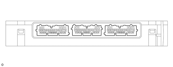
CHECK CERTIFICATION ECU (SMART KEY ECU ASSEMBLY)
3.375,0.406 3.792,0.656
0.417,0.25
4.802,0.406 5.219,0.656
0.417,0.25
1.969,0.417 2.385,0.667
0.417,0.25
4.906,0.469 5.427,0.688
0.521,0.219
10
false
E52
3.51,0.469 3.823,0.667
0.313,0.198
10
false
K6
2.073,0.479 2.385,0.677
0.313,0.198
10
false
A15
a.
Measure the voltage according to the value(s) in the table below.
| Terminal No. (Symbol) | Terminal Description | Condition | Specified Condition |
|---|---|---|---|
| E52-20 (SWIL) - E52-30 (AGND) | Push start switch illumination drive output | Push start switch illumination on | 9 to 14 V |
| Push start switch illumination off | Below 2 V |