K120 / K120F / K121 / K121F CVT OIL PAN INSTALLATION
PROCEDURE

 35015Y
1.INSTALL TRANSAXLE SIDE COVER SUB-ASSEMBLY
35015Y
1.INSTALL TRANSAXLE SIDE COVER SUB-ASSEMBLY

|
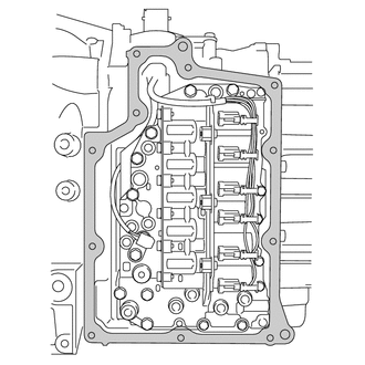
Area to be Cleaned |
Clean the transaxle side cover sub-assembly installation surface of the transaxle case sub-assembly.
- NOTICE:
-
Completely remove any oil or grease from the contact surfaces of the transaxle case sub-assembly.
Coat a new O-ring with Toyota Genuine CVT fluid FE and install it to a new transaxle side cover sub-assembly.
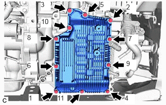
Temporarily install the transaxle side cover sub-assembly to the transaxle case sub-assembly with the 11 bolts.
Fully tighten the 11 bolts in the order shown in the illustration.
- Torque:
- 7.4 N*m (75 kgf*cm, 65 in.*lbf)
2.INSTALL WIRE HARNESS CLAMP BRACKET
Install the wire harness clamp bracket to the transaxle side cover sub-assembly with the bolt.
- Torque:
- 10 N*m (102 kgf*cm, 7 ft.*lbf)
32901L
3.INSTALL OIL COOLER ELBOW SUB-ASSEMBLY
Temporarily install the oil cooler elbow sub-assembly and 2 gaskets to the transaxle housing with the 2 union bolts.
Fully tighten the union bolt (A).
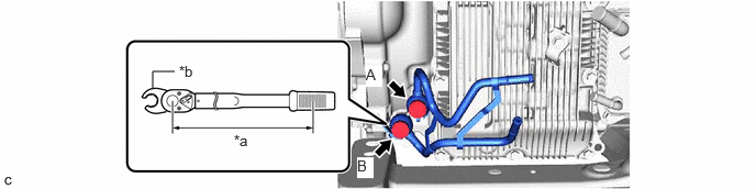
| *a | Torque Wrench Fulcrum Length | *b | 17 mm Union Nut Wrench |
- Torque:
- 27.5 N*m (280 kgf*cm, 20 ft.*lbf)
Using a 17 mm union nut wrench, fully tighten the union bolt (B).
- Torque:
- Specified Tightening Torque : 27.5 N*m (280 kgf*cm, 20 ft.*lbf)
- HINT:
- ·
Calculate the torque wrench reading when changing the fulcrum length of the torque wrench.
·When using 17 mm union nut wrench (fulcrum length of 30 mm (1.18 in.)) + torque wrench (fulcrum length of 162 mm (6.38 in.)):
23.2 N*m (237 kgf*cm, 17 ft.*lbf)
4.INSTALL OIL COOLER HOSE
Install the inlet oil cooler hose to the oil cooler elbow sub-assembly and slide the clip to secure it.
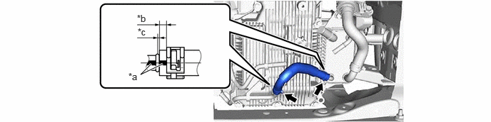
| *a | Paint Mark | *b | 2 to 7 mm (0.0787 to 0.276 in.) |
| *c | 0 to 3 mm (0 to 0.118 in.) | - | - |
- NOTICE:
- ·
Make sure to slide the inlet oil cooler hose until it contacts the hose stopper of the oil cooler elbow sub-assembly.
·Make sure to align the paint mark of the inlet oil cooler hose with the paint mark of the oil cooler elbow sub-assembly.
·Make sure that the clip is within the location shown in the illustration.
Connect the inlet oil cooler hose to the transmission oil cooler and slide the clip to secure it.
- NOTICE:
- ·
Make sure to slide the inlet oil cooler hose until it contacts the hose stopper of the transmission oil cooler.
·Make sure to align the paint mark of the inlet oil cooler hose with the paint mark of the transmission oil cooler.
·Make sure that the clip is within the location shown in the illustration.
Install the outlet No. 1 oil cooler hose to the oil cooler elbow sub-assembly and slide the clip to secure it.
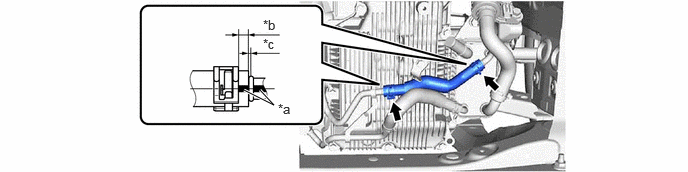
| *a | Paint Mark | *b | 2 to 7 mm (0.0787 to 0.276 in.) |
| *c | 0 to 3 mm (0 to 0.118 in.) | - | - |
- NOTICE:
- ·
Make sure to slide the outlet No. 1 oil cooler hose until it contacts the hose stopper of the oil cooler elbow sub-assembly.
·Make sure to align the paint mark of the outlet No. 1 oil cooler hose with the paint mark of the oil cooler elbow sub-assembly.
·Make sure that the clip is within the location shown in the illustration.
Connect the outlet No. 1 oil cooler hose to the transmission oil cooler and slide the clip to secure it.
- NOTICE:
- ·
Make sure to slide the outlet No. 1 oil cooler hose until it contacts the hose stopper of the transmission oil cooler.
·Make sure to align the paint mark of the outlet No. 1 oil cooler hose with the paint mark of the transmission oil cooler.
·Make sure that the clip is within the location shown in the illustration.
12361
5.INSTALL FRONT ENGINE MOUNTING INSULATOR
6.ADJUST CONTINUOUSLY VARIABLE TRANSAXLE FLUID
7.INSPECT FOR FLUID LEAKS
53737B
8.INSTALL FRONT FENDER APRON SEAL LH
51420
9.INSTALL NO. 2 ENGINE UNDER COVER ASSEMBLY