M20C-FKS, M20D-FKS ENGINE CONTROL ACTIVE CONTROL ENGINE MOUNT(for Front Side) INSTALLATION
PROCEDURE

 12361
1.INSTALL FRONT ENGINE MOUNTING INSULATOR
12361
1.INSTALL FRONT ENGINE MOUNTING INSULATOR
Install the front engine mounting insulator to the front frame assembly with the 3 nuts.
- Torque:
- 72 N*m (734 kgf*cm, 53 ft.*lbf)
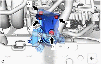
Install the front engine mounting bracket to the transaxle housing with the 3 bolts.
- Torque:
- Bolt (A), (B) and (C) : 42 N*m (428 kgf*cm, 31 ft.*lbf)
- NOTICE:
-
Temporarily tighten the bolt (A), and then fully tighten the 3 bolts in the order of (B), (C) and (A).
Install the front engine mounting bracket to the front engine mounting insulator with the bolt.
- Torque:
- Bolt (D) : 72 N*m (734 kgf*cm, 53 ft.*lbf)
Connect the vacuum hose to the front engine mounting insulator.
Engage the clamp to connect the vacuum hose to the No. 1 water by-pass hose.
2.CONNECT WIRE HARNESS
Connect the No. 6 engine wire connector and push down the lock lever to engage the claw as shown in the illustration.

| *a | Lock Lever | - | - |
Connect the 9 connectors and engage the 9 clamps.
Install the 5 bolts.
- Torque:
- Bolt (A) : 10 N*m (102 kgf*cm, 7 ft.*lbf)
- Bolt (B) : 8.0 N*m (82 kgf*cm, 71 in.*lbf)
Connect the wire harness to terminal B with the nut.
- Torque:
- 9.8 N*m (100 kgf*cm, 87 in.*lbf)
Close the terminal cap.
16261G
3.CONNECT NO. 1 WATER BY-PASS HOSE
16571C
4.CONNECT NO. 1 RADIATOR HOSE
Connect the No. 1 radiator hose to the water outlet and slide the clip to secure it.
Engage the clamp to connect the No. 1 radiator hose to the fan with motor assembly.
17650H
5.INSTALL VACUUM SWITCHING VALVE (for Active Control Engine Mount System)
51420
6.INSTALL NO. 2 ENGINE UNDER COVER ASSEMBLY
51441
7.INSTALL NO. 1 ENGINE UNDER COVER
53896B
8.INSTALL FRONT FENDER FRONT SPLASH SHIELD LH
53895B
9.INSTALL FRONT FENDER FRONT SPLASH SHIELD RH
10.CONNECT CABLE TO NEGATIVE BATTERY TERMINAL
11.ADD ENGINE COOLANT
12.INSPECT FOR COOLANT LEAK
13. INITIALIZATION AFTER RECONNECTING BATTERY TERMINAL
- HINT:
-
When disconnecting and reconnecting the battery, there is an automatic learning function that completes learning when the respective system is used.