RM36D0EC _59 Vehicle Exterior _083107 WINDOW / GLASS _0400960 POWER WINDOW CONTROL SYSTEM J

WINDOW / GLASS  POWER WINDOW CONTROL SYSTEM  Driver Side Power Window does not Operate with Power Window Master Switch  


DESCRIPTION

When the ignition switch is ON, the front power window regulator motor assembly LH is operated by the multiplex network master switch assembly. The front power window regulator motor assembly LH has motor, regulator and ECU functions.

WIRING DIAGRAM

E542364E01
1.823,1.01 2.219,1.208 0.396,0.198 10 false LIN2 2.208,0.844 2.552,1.042 0.344,0.198 10 false 15 2.24,1.469 4.688,2.031 2.448,0.563 10 false Power Distribution Box Assembly 0.792,2.24 2.448,2.708 1.656,0.469 10 false Main Body ECU (Multiplex Network Body ECU) 0.813,3.438 2.292,3.677 1.479,0.24 10 false from Auxiliary Battery 0.823,4.031 2.302,4.271 1.479,0.24 10 false from Auxiliary Battery 2.781,3.615 3.688,3.844 0.906,0.229 10 false ECU-B NO.2 2.854,4.219 3.688,4.427 0.833,0.208 10 false DOOR F/L 4.385,3.344 4.729,3.542 0.344,0.198 10 false 11 4.708,3.344 5.052,3.542 0.344,0.198 10 false B 5.521,3.198 5.865,3.396 0.344,0.198 10 false +B 5.865,3.667 6.354,3.938 0.49,0.271 10 false LIN1 6.26,3.49 6.604,3.688 0.344,0.198 10 false 17 5.51,3.792 5.854,3.99 0.344,0.198 10 false 12 V 5.802,4.417 6.146,4.615 0.344,0.198 10 false 5 V 5.208,4.833 5.656,5.198 0.448,0.365 10 false Control Circuit 4.719,5.49 5.146,5.719 0.427,0.229 10 false LIN2 4.719,5.99 5.063,6.188 0.344,0.198 10 false UP 4.708,6.479 5.229,6.719 0.521,0.24 10 false DOWN 5.813,6.938 6.208,7.135 0.396,0.198 10 false GND 6.25,6.792 6.594,6.99 0.344,0.198 10 false 12 4.646,7.708 6.229,8.063 1.583,0.354 10 false Multiplex Network Master Switch Assembly 4.375,5.292 4.719,5.49 0.344,0.198 10 false 16 4.375,5.865 4.719,6.063 0.344,0.198 10 false 20 4.365,6.375 4.708,6.573 0.344,0.198 10 false 15 2.813,4.906 3.156,5.104 0.344,0.198 10 false 2 2.813,5.313 3.156,5.51 0.344,0.198 10 false 9 2.771,5.844 3.115,6.042 0.344,0.198 10 false 10 2.802,6.354 3.146,6.552 0.344,0.198 10 false 7 2.792,6.792 3.135,6.99 0.344,0.198 10 false 1 2.323,6.792 2.667,6.99 0.344,0.198 10 false GND 2.177,6.365 2.677,6.573 0.5,0.208 10 false DOWN 2.427,5.854 2.771,6.052 0.344,0.198 10 false UP 2.406,5.313 2.813,5.521 0.406,0.208 10 false LIN 2.531,4.917 2.875,5.115 0.344,0.198 10 false B 1.292,6.01 1.635,6.208 0.344,0.198 10 false IC 1.292,6.323 1.635,6.521 0.344,0.198 10 false IC 0.906,7.656 2.823,8.01 1.917,0.354 10 false Front Power Window Regulator Motor Assembly LH 0.76,8.406 2.396,8.646 1.635,0.24 10 false : LIN Communication Line 4.646,7.521 4.958,7.719 0.313,0.198 10 false J2 0.906,7.49 1.365,7.688 0.458,0.198 10 false J6 0.823,2.063 0.979,2.26 0.156,0.198 10 false A

CAUTION / NOTICE / HINT

NOTICE:
·

The power window control system uses the LIN communication system. Inspect the communication function by following How to Proceed with Troubleshooting. Troubleshoot the power window control system after confirming that the communication system is functioning properly.

Click hereVehicle Exterior>WINDOW / GLASS>POWER WINDOW CONTROL SYSTEM>HOW TO PROCEED WITH TROUBLESHOOTING

·

If the front power window regulator motor assembly LH has been replaced with a new one, initialize the power window control system.

Click hereVehicle Exterior>WINDOW / GLASS>POWER WINDOW CONTROL SYSTEM>INITIALIZATION

·

Inspect the fuses for circuits related to this system before performing the following procedure.


PROCEDURE

1.READ VALUE USING GTS (D-DOOR MOTOR)
a.

Read the Data List according to the display on the GTS.

Click hereVehicle Exterior>WINDOW / GLASS>POWER WINDOW CONTROL SYSTEM>DATA LIST / ACTIVE TEST

Body Electrical > D-Door Motor > Data List
Tester Display Measurement Item Range Normal Condition Diagnostic Note
D Door P/W Up SW Driver door power window manual up switch signal OFF or ON OFF: Driver door power window manual up switch not being operated
ON: Driver door power window manual up switch being operated
-
D Door P/W Down SW Driver door power window manual down switch signal OFF or ON OFF: Driver door power window manual down switch not being operated
ON: Driver door power window manual down switch being operated
-
Body Electrical > D-Door Motor > Data List
Tester Display
D Door P/W Up SW
D Door P/W Down SW
50003 124 2,3
OK:

On the GTS screen, ON or OFF is displayed accordingly.


Result:
Proceed to
OK
NG


OK

NG

2.CHECK MULTIPLEX NETWORK MASTER SWITCH ASSEMBLY
a.
B527907C13
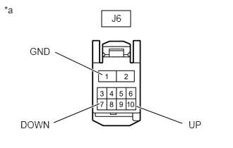
1.5,0.156 1.927,0.396 0.427,0.24 0.813,0.771 1.51,1.104 true 0.792,1.813 1.469,1.531 true 2.688,1.823 1.99,1.563 true 0.063,0.063 0.375,0.219 0.313,0.156 10 false *a 1.646,0.188 2.104,0.385 0.458,0.198 10 false J6 0.438,0.677 0.896,0.875 0.458,0.198 10 false GND 0.302,1.76 0.823,1.979 0.521,0.219 10 false DOWN 2.781,1.76 3.042,1.979 0.26,0.219 10 false UP
*a Front view of wire harness connector
(to Front Power Window Regulator Motor Assembly LH)


Disconnect the J6 front power window regulator motor assembly LH connector.


b.

Measure the voltage according to the value(s) in the table below.

Standard Voltage:
Tester Connection Condition Specified Condition
J6-10 (UP) - J6-1 (GND)
·

Ignition switch turned to ON

·

Multiplex network master switch assembly (driver side switch) OFF → UP (manual operation)


11 to 14 V → Below 1 V
J6-7 (DOWN) - J6-1 (GND)
·

Ignition switch turned to ON

·

Multiplex network master switch assembly (driver side switch) OFF → DOWN (manual operation)


11 to 14 V → Below 1 V


Result:
Proceed to
OK
NG


OK

NG

3.CHECK HARNESS AND CONNECTOR (MULTIPLEX NETWORK MASTER SWITCH ASSEMBLY - FRONT POWER WINDOW REGULATOR MOTOR ASSEMBLY LH)
a.

Disconnect the J2 multiplex network master switch assembly connector.


b.

Disconnect the J6 front power window regulator motor assembly LH connector.


c.

Measure the resistance according to the value(s) in the table below.

Standard Resistance:
Tester Connection Condition Specified Condition
J2-20 (UP) - J6-10 (UP) Always Below 1 Ω
J2-15 (DOWN) - J6-7 (DOWN) Always Below 1 Ω
J2-20 (UP) or J6-10 (UP) - Body ground Always 10 kΩ or higher
J2-15 (DOWN) or J6-7 (DOWN) - Body ground Always 10 kΩ or higher


Result:
Proceed to
OK
NG


OK

NG

REPAIR OR REPLACE HARNESS OR CONNECTOR