STEERING GEAR / LINKAGE STEERING GEAR INSTALLATION
CAUTION / NOTICE / HINT
- NOTICE:
- for GTMC Made:
- ·
After replacing the rack and pinion power steering gear assembly, make sure to perform update ECU security key.
·After performing the update ECU security key procedure, make sure to perform the initialization procedure for when the cable has been disconnected and reconnected to the negative (-) auxiliary battery terminal.
- NOTICE:
- for SFTM Made:
-
After replacing the rack and pinion power steering gear assembly, make sure to perform torque sensor zero point calibration.
PROCEDURE

 45470
1.TEMPORARILY INSTALL TIE ROD ASSEMBLY LH
45470
1.TEMPORARILY INSTALL TIE ROD ASSEMBLY LH
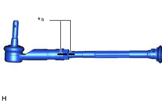
| *a | Matchmark |
Temporarily install the lock nut and tie rod assembly LH to the rack and pinion power steering gear assembly until the matchmarks are aligned.
- HINT:
-
After adjusting the toe-in, tighten the lock nut.
45460
2.TEMPORARILY INSTALL TIE ROD ASSEMBLY RH
- HINT:
-
Perform the same procedure as for the LH side.
3.INSTALL RACK AND PINION POWER STEERING GEAR ASSEMBLY
Install the rack and pinion power steering gear assembly to the front frame assembly with the 4 bolts and 4 new nuts.
- Torque:
- 88 N*m (897 kgf*cm, 65 ft.*lbf)
- NOTICE:
-
Because the nut has its own stopper, do not turn the nut. Tighten the bolt with the nut secured.
4.INSTALL FRONT STABILIZER BAR WITH BRACKET
Install the front stabilizer bar with 2 front stabilizer links, front No. 1 stabilizer bracket LH, front No. 1 stabilizer bracket RH and 2 front No. 1 stabilizer bar bushings to the front frame assembly.
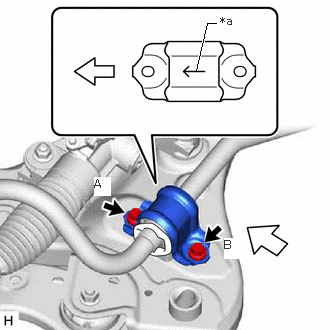
| *a | Arrow |

|
Front of the Vehicle |
Install the front No. 1 stabilizer bracket LH to the front frame assembly with the 2 bolts.
- Torque:
- 44 N*m (449 kgf*cm, 32 ft.*lbf)
- NOTICE:
- ·
Make sure to install the front No. 1 stabilizer bracket LH with its arrow facing the front of the vehicle.
·Temporarily install the bolt (B) and then tighten the 2 bolts in the order of (A) and (B).
Install the front No. 1 stabilizer bracket RH to the front frame assembly with the 2 bolts.
- HINT:
-
Perform the same procedure as for the LH side.
51021A
5.INSTALL FRONT ENGINE SUPPORT MEMBER SUB-ASSEMBLY
6.CONNECT WIRE HARNESS
Install the wire harness to the rack and pinion power steering gear assembly with the 2 bolts.
- Torque:
- 10 N*m (102 kgf*cm, 7 ft.*lbf)
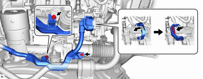
Connect the wire harness connector to the rack and pinion power steering gear assembly.
- HINT:
-
Make sure that the connector is fully inserted before rotating the lock lever to engage the lock.
45319
7.INSTALL STEERING GEAR HEAT INSULATOR
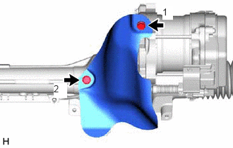
Install the steering gear heat insulator to the rack and pinion power steering gear assembly with the 2 bolts in the order shown in the illustration.
- Torque:
- 8.0 N*m (82 kgf*cm, 71 in.*lbf)
8.INSTALL ENGINE ASSEMBLY WITH TRANSAXLE
45470
9.CONNECT TIE ROD ASSEMBLY LH
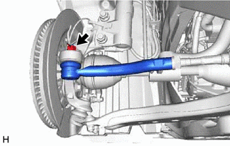
Connect the tie rod assembly LH to the steering knuckle LH with the nut.
- Torque:
- 49 N*m (500 kgf*cm, 36 ft.*lbf)
- NOTICE:
- ·
Do not damage the ball joint dust cover.
·Further tighten the nut up to 60° if the holes for the cotter pin are not aligned.
Install a new cotter pin.
45460
10.CONNECT TIE ROD ASSEMBLY RH
- HINT:
-
Perform the same procedure as for the LH side.
45220
11.CONNECT STEERING INTERMEDIATE SHAFT ASSEMBLY
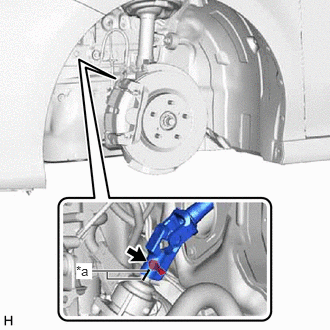
| *a | Matchmark |
Align the matchmarks on the steering intermediate shaft assembly and rack and pinion power steering gear assembly.
Connect the steering intermediate shaft assembly to the rack and pinion power steering gear assembly.
Install the bolt.
- Torque:
- 35 N*m (357 kgf*cm, 26 ft.*lbf)
12.INSTALL FRONT WHEELS
13.INSPECT AND ADJUST FRONT WHEEL ALIGNMENT
45470
14.FULLY TIGHTEN TIE ROD ASSEMBLY LH
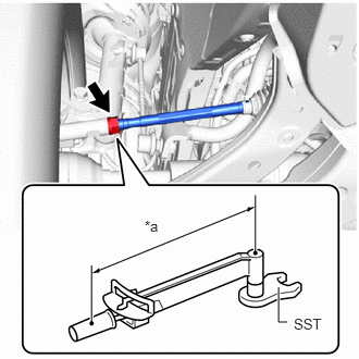
| *a | Torque Wrench Fulcrum Length |
Using SST, tighten the tie rod end assembly lock nuts.
- SST
- 09612-24014 (09617-24011)
- Torque:
- Specified Tightening Torque : 88 N*m (897 kgf*cm, 65 ft.*lbf)
- NOTICE:
-
Make sure that the boots are not twisted.
- HINT:
- ·
Calculate the torque wrench reading when changing the fulcrum length of the torque wrench.
·When using SST (fulcrum length of 52 mm (2.0472 in.)) + torque wrench (fulcrum length of 380 mm (14.9606 in.)):
77.4 N*m (789 kgf*cm, 57 ft.*lbf)
45460
15.FULLY TIGHTEN TIE ROD ASSEMBLY RH
- HINT:
-
Perform the same procedure as for the LH side.
16. UPDATE ECU SECURITY KEY
If the rack and pinion power steering gear assembly has been replaced, perform update ECU security key.
17. POWER STEERING ECU INITIAL SETTING
When replacing the rack and pinion power steering gear assembly, perform the power steering ECU initial setting.
18. INITIALIZATION AFTER RECONNECTING BATTERY TERMINAL
- HINT:
-
When disconnecting and reconnecting the auxiliary battery, there is an automatic learning function that completes learning when the respective system is used.