DOOR / HATCH POWER BACK DOOR SYSTEM Power Back Door cannot be Operated Using Kick Sensor
DESCRIPTION
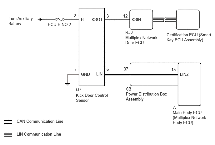
The kick door control sensor uses LIN communication and stops sensor output based on the vehicle speed, ignition switch ON (IG) or ON (ACC) signals sent from the multiplex network door ECU.
When the kick door control sensor detects a kick operation, it sends an operation signal to the multiplex network door ECU.
WIRING DIAGRAM
CAUTION / NOTICE / HINT
- NOTICE:
- ·
If the multiplex network door ECU has been replaced, or if any of the connectors has been disconnected, initialize the power back door system.
·First perform the communication function inspections in How to Proceed with Troubleshooting to confirm that there are no CAN communication malfunctions before troubleshooting this problem.
·Check the smart entry and start system (for Entry Function) first before troubleshooting the power back door system.
for Entry Function, HV Model:
for Entry Function, Gasoline Model:
·Inspect the fuses for circuits related to this system before performing the following inspection procedure.
PROCEDURE
Operate the multi-information display and check the customization status.
| Display | Description | Default | Setting | Relevant ECU |
|---|---|---|---|---|
| System Settings | Function that enables or disables the power back door operation. | On | On or Off | Multiplex network door ECU |
| Hands Free | Function that can be used to set the hands free power back door. | On | On or Off | Multiplex network door ECU |
- Result:
Result Proceed to Customization item is "On" A Customization item is "Off" B
A
B
Check the power back door system.
- Result:
Result Proceed to Power back door system operates normally A Power back door system does not operate normally B
A
B
Clear the DTCs.
- Body Electrical > Back Door > Clear DTCs
- 50002 489
- Result:
Proceed to NEXT
NEXT
Turn the ignition switch to ON and wait for at least 10 seconds.
- Result:
Proceed to NEXT
NEXT
Check for DTCs.
- Body Electrical > Back Door > Trouble Codes
- 50001 489
- Result:
Result Proceed to DTC is output A DTC is not output B
A
B
Read the Data List according to the display on the GTS.
- Body Electrical > Back Door > Data List
-
Tester Display Measurement Item Range Normal Condition Diagnostic Note Kick Sensor Error Status of the kick door control sensor error Normal or Error Normal: Kick door control sensor normal
Error: Kick door control sensor abnormal-
- Body Electrical > Back Door > Data List
-
Tester Display Kick Sensor Error - 50003 159 77
- OK:
On the GTS, Normal is displayed.
- Result:
Proceed to OK NG
OK
NG
Click hereVehicle Exterior>DOOR / HATCH>KICK SENSOR>REMOVAL202409,999999,_59,_083093,_0417406,RM100000002NG1U,
Read the Data List according to the display on the GTS.
- Body Electrical > Back Door > Data List
-
Tester Display Measurement Item Range Normal Condition Diagnostic Note Kick Sensor Detection Status of the kick door control sensor detection OFF or ON OFF: Kick door control sensor not detecting a foot
ON: Kick door control sensor detecting a foot-
- Body Electrical > Back Door > Data List
-
Tester Display Kick Sensor Detection - 50003 159 76
- OK:
On GTS screen, item changes between ON and OFF according to above chart.
- Result:
Proceed to OK NG
OK
NG
Disconnect the Q7 kick door control sensor connector.
Disconnect the 6B power distribution box assembly connector.
Measure the resistance according to the value(s) in the table below.
- Standard Resistance:
Tester Connection Condition Specified Condition Q7-6 (LIN) - 6B-37 Always Below 1 Ω
- Result:
Proceed to OK NG
OK
NG
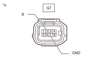
| *a | Front view of wire harness connector
(to Kick Door Control Sensor) |
Disconnect the kick door control sensor connector.
Measure the resistance according to the value(s) in the table below.
- Standard Resistance:
Tester Connection Condition Specified Condition Q7-7 (GND) - Body ground Always Below 1 Ω
Measure the voltage according to the value(s) in the table below.
- Standard Voltage:
Tester Connection Switch Condition Specified Condition Q7-2 (B) - Body ground Ignition switch off 11 to 14 V
- Result:
Proceed to OK NG
OK
NG
Disconnect the Q7 kick door control sensor connector.
Disconnect the R30 multiplex network door ECU connector.
Measure the resistance according to the value(s) in the table below.
- Standard Resistance:
Tester Connection Condition Specified Condition Q7-3 (KSOT) - R30-12 (KSIN) Always Below 1 Ω Q7-3 (KSOT) or R30-12 (KSIN) - Body ground Always 10 kΩ or higher
- Result:
Proceed to OK NG
OK
NG
Remove the multiplex network door ECU with the connector(s) still connected.
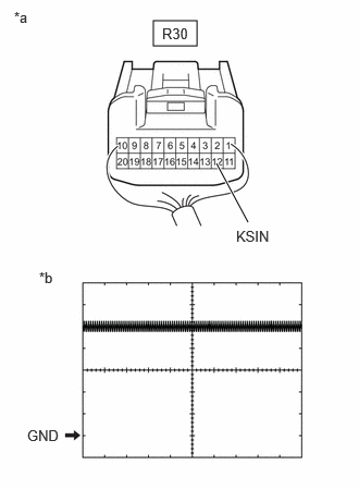
| *a | Component with harness connected
(Multiplex Network Door ECU) |
| *b | Waveform |
Check the signal waveform according to the condition(s) in the table below.
| Item | Condition |
|---|---|
| Tester Connection | R30-12 (KSIN) - Body ground |
| Tool Setting | 2 V/DIV., 50 ms./DIV. |
| Vehicle Condition | Ignition switch ON, kick door control sensor not detecting a foot |
- OK:
The waveform displayed is as shown in the illustration.
- Result:
Proceed to OK NG
OK
Click hereVehicle Exterior>DOOR / HATCH>KICK SENSOR>REMOVAL202409,999999,_59,_083093,_0417406,RM100000002NG1U,
NG